Cover Image Credit – Sajad-HasanAhmadi, TV antenna connectors, CC BY-SA 4.0
Points of Discussion: Transmission Line
- Introduction
- Purpose of transmission line
- Analysis of transmission line
- Types of transmission line
- Applications of transmission lines
Introduction to Transmission Line
A transmission line is a specially designed cable for transmission of power. It conducts only electromagnetic waves to the load at low frequencies in a guided way.
Transmission line operates at microwave frequency domain and radio frequency domain where power is assumed as an electromagnetic wave. That is why if any cable can guide an electromagnet signal, then it will be called a Transmission line.
The transmission line is the result of researches of James Maxwell, Lord Kelvin, and Oliver Heaviside. The fault and drawbacks of the ‘Atlantic telegraph cable’ and invention of telegrapher’s equation made the way out for the line.
Purpose of transmission line
Regular cables which transfer electrical energy are designed to conduct power at lower frequency AC. They cannot carry power in FR range or above 30 kilo hertz as the energy gets disconnected at joints and connectors, and some time does not reach the destination. This lines resolve these problems. They are constructed specially to minimize the reflections and loss of power and also uses the impedance matching to carry power.
This lines are constructed with a uniform cross-sectional area. That is why they provide uniform impedance which is in terms known as characteristic impedance.
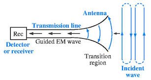
Use of Transmission Line in antenna
The wavelength of the electromagnetic waves gets shorter as the frequency gets higher of the electromagnetic waves. Transmission lines are crucial because when the wavelength is short enough, the length of the wire contributes to the past of the wavelength.
What is a Yagi Uda Antenna? Click here for details!
Analysis of Transmission line
We assume a four-terminal model of the transmission lines to analyze the construction and working of lines. It is equivalent to a typical two-port circuit.
We assume that the circuit is linear, which means that the complex voltage at any port is relational to the complex current for the reflectionless condition. Also, we assume that two of its ports are transposable.
Characteristics impedance of transmission line
Characteristic impedance or (Z0) is an essential parameter of the line. It can be defined as the ratio of the magnitude of the voltage to the magnitude of the current of a wave, travelling along a reflection less line.
Characteristics impedance controls the behaviors of the line only if the line is uniform in length. Generally, for co-axial cables, characteristic impedance has a value of fifty to seventy ohms, and for warped pair of wires, the value is 100 ohms. For untwisted pair, the value is 300 ohms.
Transmission line reflection coefficient
The line’s reflection coefficient is given by the ratio of the complex magnitude of the reflected signal to the incoming signal. It is represented by the Greek alphabet – Г and expressed as –
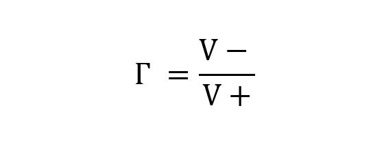
where V+ is the complex voltage of the incoming voltage and V- is the complex voltage of the reflected wave.
It has a relation with the load impedance and characteristic impedance. The expression is given below.
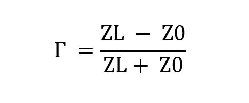
Here ZL is the load impedance, and Z0 is the characteristic impedance.
The standing wave ratio also has a relation with this line reflection coefficient. The connection is given as –
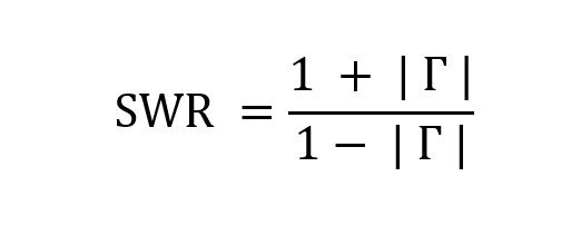
The relation between Standing Wave Ratio and transmission line reflection coefficient.
Matched condition of transmission line:
The aim of a transmission line is to deliver the maximum power from the source to destination load and to minimize the reflection and loss of the power. The ‘matched’ condition can fulfil this desired. If the destination’s load impedance is made same or equal to the value of the characteristic impedance of the line, then the line achieves ‘matched’ condition.
Instead of the ‘matched’ condition, the transmission suffers some loss. Like, ohmic loss. There is also another substantial loss that occurs when this line works in high frequency ranges. The loss is known as dielectric loss. Here, the inside elements of this lines, grips the EM energy and produces heat.
The aggregate loss of this line is measured by the unit dB/m. The losses are dependent on the frequency of the signal, as mentioned earlier. The constructor companies of this usually provide a chart of loss. It shows the loss of power at different frequencies. If any line suffers a loss of three decibel/meter, then the power received at the load will be half of the power supplied.
What is horn antenna? get an overview here!
Types of transmission lines
These come with certain types depending upon its physical structure and according to the needs. Some of the essential and widely used types of transmission lines are listed below. Please go through it and discover them.
Co-axial cables:
It is one of the widely used forms of lines. It restricts the whole EM wave inside the cable. Thus, co-axial cables can be bent, strapped as well as twisted to an extent without affecting the operation.

Cross-section of a Co-axial Cables, Image Credit: Tkgd2007, Coaxial cable cutaway, CC BY 3.0
EM waves promulgate in TEM or transverse electric and magnetic mode For the RF range applications. Here, both the electric and magnetic fields are perpendicular with the promulgate directions. The electric field becomes radiated, and the magnetic field becomes circumferential.
If the wavelength of the wave is shorter than the circumference of the co-axial cable, then the TEM gets divided into two. The modes are then known as TE or transverse electric and TM or transverse magnetic.
Co-axial cables have broad applications for televisions. It was primarily used for telephones in the middle of twenty century.
Microstrip transmission lines:
A microstrip network is basically a tiny conductive plane, placed parallelly to the ground surface. It can be designed by putting a thin and flat metallic plane on the side of a PCB. The opposite surface must be the ground plane. The characteristic impedance of the microstrip type line depends on that conductive strip. The height, width, dielectric coefficient of the conductive strip provides the characteristic impedance. A point to be remembered that the microstrip type line is an open structure while the co-axial cable is a closed one.
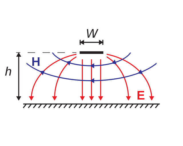
Electric & Magnetic field of Microstrip Transmission Line,
Image Credit: Dassault
Twisted pair transmission lines:
In this type of line where pairs of wire are assembled together to form a single chain or a cable is known as tangled pair transmission lines. These types of lines are used in global telephonic communications. Also, it has used in data circulation inside buildings. This type is not economical due to its properties.
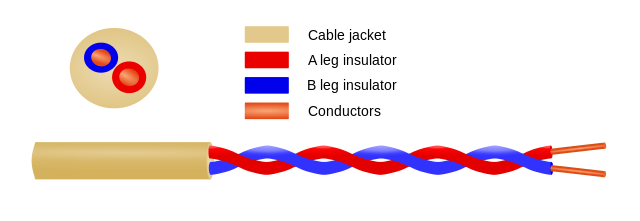
Image of a Twisted Pair types. Image Credit – Spinningspark at en.wikipedia, Twisted pair, CC BY-SA 3.0
Star quad:
Star quad is another wire-combinational formation. It uses four cables, and all the conductors of the four cables are twisted and assembled along the axis of the cable. In this formation, each and every pairs uses a far pair to get connected.
The combinational form of twisted, balancing and quadrupole pattern of transmission lines has several benefits as it reduces noise, particularly for short signal level usage like – cables of the microphone.
Descriptive image of a star quad cable, Image Source – Spinningspark at en.wikipedia, DM quad, CC BY-SA 3.0
This type of line has applications in four-wire telephony, two-wire applications.
It also induces high capacitance which further causes distortion and losses.
Applications of transmission lines | Uses of transmission lines
Transmission lines have several benefits over regular electrical cables in specific domains. That is why it has several applications. Let us discuss some of them.
- Electromagnetic powers are supplied in high frequency domains with minimum loss. Tv and radio cables for connecting the aerials is one of the most famous examples.
- These are also used for the generation of pulses by charging and discharging this lines. A significant example of this type of line is – Blumlein Transmission Line. Radars have also multiple application of this kind.
- These are also applied in stub filters. Stub filters are typically wired in a parallel connection and transfer power from the source to destinations.
Check out more on Electronics! Click Here!

Hi, I am Sudipta Roy. I have done B. Tech in Electronics. I am an electronics enthusiast and am currently devoted to the field of Electronics and Communications. I have a keen interest in exploring modern technologies such as AI & Machine Learning. My writings are devoted to providing accurate and updated data to all learners. Helping someone in gaining knowledge gives me immense pleasure.
Let’s connect through LinkedIn –