- summing operational amplifier
- summing amplifier definition
- non inverting summing amplifier
- inverting summing amplifier
- summing amplifier circuit
- inverting summing amplifier circuit
- non inverting summing amplifier circuit
- summing amplifier with ac and dc input
- summing amplifier output
- summing amplifier waveform
- summing amplifier output waveform
- gain of a summing amplifier
- determine the output voltage of the summing amplifier
- summing amplifier derivation
- inverting summing amplifier formula
- non inverting summing amplifier derivation
- summing amplifier gain formula
- summing amplifier ic
- summing amplifier schematic
- analog summing amplifier
- summing and difference amplifier theory
- audio summing amplifier
- current summing-amplifier
- difference between inverting and non inverting summing amplifier
- digital to analog converter summing-amplifier
- function of summing amplifier
- single supply summing-amplifier
- summing-amplifier applications
- summing amplifier audio mixer
- summing amplifier dc offset
- summing amplifier design
- summing-amplifier example
- summing scaling and averaging amplifier
- summing amplifier circuit on breadboard
- FAQs
Summing operational amplifier
A summing-amplifier is one of the op-amp applications, which performs summation or addition operations. Multiple input voltages are supplied into the amplifier, and the output provides an amplified summation of the voltages. Summing-amplifiers has various applications in electronics. It also has two types – inverting summing-amplifier and non-inverting summing-amplifier. In detail, we will discuss the analysis of the summing-amplifier in the following article.

Image credit : Wikipedia commons
Summing amplifier definition
A summing-amplifier can be defined as An amplifier, which takes multiple inputs at one of the input terminals and provides the weighted sum of all the inputs.
Non inverting summing amplifier using op amp
Non-inverting summing-amplifier is one of the types of summing-amplifiers. In this type of operations, the input voltages are provided in the amplifier’s non-inverting terminal. The polarity of the output remains the same as the inputs and because of this, it is termed as non-inverting summing-amplifier.
Inverting summing amplifier
Inverting summing-amplifier is another type of summing-amplifier where the input voltages are provided in the inverting terminals. The polarity of the output voltages gets changed and for that reason it is known as inverting summing-amplifier.
Summing amplifier design
A summing-amplifier is designed with the help of a basic op amp and resistances. It can be designed in two main configurations
- inverting summing-amplifier.
- non-inverting summing-amplifier.
We will discuss the general designing of a summing-amplifier.
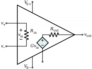
To design a circuit with an op-amp, we have to keep in mind the op-amp’s basic properties. They are – high input impedance and the concept of virtual ground. For the virtual ground, we have to make a ground connection in any input terminal (the conventional way is to connect the ground in the opposite terminal where inputs are not supplied). A feedback path is created, keeping in mind the high input gain. Generally, a negative feedback path is made for system stability. The Inputs are provided with resistances. The output is collected from the output, containing the weighted sum of input.
Summing amplifier circuit | Op amp summing amplifier circuit design
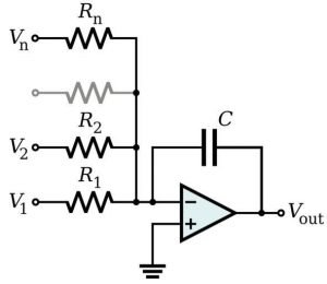
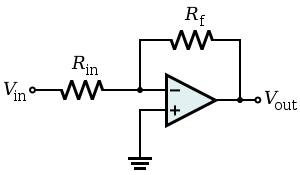
The below images represent circuit diagrams of the summing-amplifier. The first one is for inverting the summing-amplifier circuit, and the second is for the non-inverting summing-amplifier circuit.
Inverting summing amplifier circuit

Non inverting summing amplifier circuit

Observe both the circuit diagram as you can observe the difference in applying the input voltages.
Summing amplifier with ac and dc input
A summing-amplifier can be provided with either ac voltage or dc voltage. The input voltage types generally have no in the operation of the amplifier.
Summing amplifier output
The output of a summing-amplifier provides the amplified added up input voltages provided at one of the op amp input terminals. The polarity of the output voltage depends on selecting the input terminal and if the input is provided in the non-inverting terminal, the output will not be inverted. Still, if the input is provided in the inverting terminal of the circuit, there will be a polarity change.
Summing amplifier waveform
The input and output voltages of an op-amp can be observed and measured using a CRO. The CRO pins are connected with the input pins and the ground for observing the input voltages.
Summing-amplifier output waveform
To observe the output, the positive jack of the CRO is connected to the output pin, and the Negative jack is connected to the ground pin. Then we can observe the output voltage.
Gain of a summing-amplifier
The summing-amplifier is also a typical op-amp. It also amplifies the input signal and provides the output. Now, a summing-amplifier also performs the addition operation. So, it amplifies the summed-up input voltage. The general equation (of non-inverting summing amplifier) can be written as: Vo = k (V1 + V2 + … + Vn). Here, Vo is the output equation and V1, V2 … Vn are the input voltages. ‘k’ is the gain factor.
How to determine the output voltage of the summing-amplifier?
A few steps are to be followed to determine the O/P voltage of the summing-amplifier. At first, we have to use the concept of virtual ground. Using this, we make sure that voltages at both the input terminal are equal. Then apply Kirchhoff’s Current Law to get the voltage equations from the input terminals. After that, replace the necessary terms to get the final output in input voltages and resistances. Derivations for both the inverting and non-inverting types are given below.
Summing-amplifier derivation
The derivation of the summing-amplifier refers to the output equation’s derivation. The derivation includes finding out the current equation using KCL and using the concept of virtual ground ad high input impedance wherever applicable. The derivation of inverting and non-inverting summing-amplifier is done below.
Inverting summing amplifier formula
Let us determine the output formula for an inverting summing-amplifier, having ‘n’ number of inputs. Observe the circuit diagram given above.
Using the virtual ground concept, the A node’s potential is identical to potential at the B node. Applying KCL, current will be
I1 +I2 +I3 +…+IN = IO
Or, V1 /R1 + V2/R2 + … +Vn/Rn = – Vo/Rf
Or, Vo = – [(V1*Rf/R1) + (Rf*V2/R2) + … + (Rf*Vn/Rn)
Now if R1 = R2 = … = Rn = Rf, then we can write –
Vo = – [V1 + V2 + … +Vn]
This is the inverting summing-amplifier formula.
Non inverting summing-amplifier derivation
Observe the circuit diagram of the non-inverting summing-amplifier. The feedback resistance is given as Rf. The resistances for every input voltage are assumed as R1 =R2 = R3 = R. The resistance for inverting summing-amplifier is R1. Using, the concept of virtual ground and KCL, the output equation comes as: Vo = [1 + (Rf/R1)] * [ (V1 + V2 + V3)/3]
Summing-amplifier gain formula
The output equation of an inverting summing-amplifier is given as:
Vo = – [(V1*Rf/R1) + (Rf*V2/R2) + … + (Rf*Vn/Rn)
Assuming R1 = R2 = … = Rn,
Vo = – [(V1*Rf/R1) + (Rf*V2/R1) + … + (Rf*Vn/R1)
Or, Vo = – (Rf/R1) [ V1 + V2 + … + Vn]
Now, the General equation of an inverting amplifier is:
Vo = – k (V1 + V2 + … + Vn), Where k is the gain.
So, k = (Rf/R1)
It is the gain factor of an inverting summing-amplifier.
Summing-Amplifier IC
There is no readymade summing-amplifier available in IC packaging. They are build using the conventional op-amp ICs. Op-amps, like LM358, which has a dual op-amp implemented in it, are used to make the circuit.
Summing amplifier schematic
The schematic diagram of the summing-amplifier is given below.

Analog summing-amplifier
The amplifier is an analog device. A summing-amplifier is also used for digital to analog conversion. That is why summing-amplifiers are called analog summing amplifiers.
Summing and difference amplifier theory
The theory behind summing and difference amplifier is just the mathematical operations of addition and subtraction. In the summing-amplifiers, input voltages are provided at one end, and the output, the sum of the voltages, is received with some amplification in the output.
Same for difference amplifier, two or more voltages are provided at the input stage, and an output, the difference between them is provided with amplifications.
Both the amplifiers are also basic op-amps. So, the theory and principles of basic op-amps are also followed.
Summing amplifier uses
A summing-amplifier is a handy device. As the name recommends, the amplifier mixes up signals as required. Some of the significant applications are-
- Audio Mixer: Summing-amplifiers are used in audio mixing for adding up various inputs with equal gains.
- DAC: Summing-amplifiers are also used in Digital to Analog Converters.
- Analog Signal Processing: Summing-amplifiers are efficient instruments for signal processing.
Audio summing amplifier
Audio summing-amplifier is one of the significant applications of summing-amplifiers. Audio amplifiers mix up vocals, drums, guitars and other sounds from other instruments. It is one of the essential devices for playback recordings.
DC summing-amplifier
The Dc summing-amplifier is referred to as the summing-amplifiers fed with the input dc voltages. In general, summing-amplifiers can be fed with either ac or dc voltages for their operation.
Difference between inverting and non inverting summing amplifier
Inverting and non-inverting summing-amplifiers are nothing but two different summing-amplifiers configurations and comparison in-between as follows:
| Subject of Comparison | Inverting Summing-Amplifier | Non-inverting Summing-Amplifier |
| Input | Input is applied in the inverting terminal of the circuit. | Input is applied to the non-inverting amplifier of the circuit. |
| Output | The output polarity gets inverted from the input. | The output polarity remains the same as the input terminal signal. |
| Preferences | An inverting summing-amplifier is more preferred comparatively. | A non-inverting summing-amplifier is used in specific applications. |
Differential summing-amplifier
A summing-amplifier provides an output that includes the weighted sum of inputs. Now, suppose the output of a summing-amplifier has both the negative polarity input and positive polarity voltages. In that case, that summing amplifier will be known as a differential summing-amplifier. Such amplifiers can be designed and are readily available in the market.
Digital to analog converter summing-amplifier
A digital to analog converter converts the provided digital signal into its equivalent analog signal and to know more about digital to analog converter, Click Here.
A summing-amplifier is an essential device for making a digital to analog converter, circuit diagram of a 3-bit DAC using a summing-amplifier has been shown here.
<image:4>
The output of the circuit comes as: Vo = -R [(V2/R) +(V1/2R) + (V0 / 4R)]
After simplifying the equation, we can write –
Vo = -1/4[ 4V2 + 2V1 + V0]
The output table
| V2 | V1 | V0 | Digital Value | Vout (Analog Value) |
| 0 | 0 | 0 | 0 | 0 |
| 0 | 0 | 1 | 1 | -0.25 |
| 0 | 1 | 0 | 2 | -0.5 |
| 0 | 1 | 1 | 3 | -0.75 |
| 1 | 0 | 0 | 4 | -1.0 |
| 1 | 0 | 1 | 5 | -1.25 |
| 1 | 1 | 0 | 6 | -1.5 |
| 1 | 1 | 1 | 7 | -1.75 |
Function of summing-amplifier
The summing-amplifier’s function is to add all the input voltages provided at either inverting or non-inverting terminal and provided the output, which contains the weighted sum of all the input.
How does a summing-amplifier work
The working of a summing-amplifier is straightforward. Inputs are given at one of the input terminals. The resistances add weight to the input voltages. The amplifier then sums up all the weighted input and produces output.
Summing-amplifier dc offset
A summing-amplifier is supplied with a DC offset voltage with an AC voltage. This supply helps maintain the LEDs in the LED modulation circuit, working in a linear range.
Summing-amplifier example
Some of the examples of summing-amplifiers are Audio mixers, Digital to analog converters, LED modulations, voltage adder, etc.
Summing scaling and averaging amplifier
Inverting amplifier has three types of configurations. They are – summing, averaging, and scaling. We have discussed inverting the summing-amplifier. Now we are going to describe the scaling and averaging.
The output equation of the inverting summing-amplifier is:
Vo = – [(V1*Rf/R1) + (Rf*V2/R2) + … + (Rf*Vn/Rn)
Now, observe. The resistance term associated with the input voltages contributes to the gain and effecting the output. Change in the resistance will change the output. This is the scaling amplifier.
Now, if R1= R2 = … =Rn = R,
Then, Vo = – [(V1*Rf/R) + (Rf*V2/R) + … + (Rf*Vn/R)
Or, Vo = – (Rf/R) [V1+ V2+ … + Vn]
Now, if (Rf / R) = 1/n, where n is the number of input, Then the equation comes as: Vo = – (1/n) [V1+ V2+ … + Vn]
We can say this equation represents the average of all the input signal. This is the averaging amplifier.
Summing-amplifier circuit on breadboard
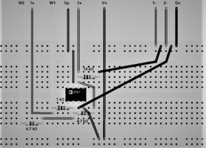
A summing-amplifier (either inverting or non-inverting) adding up two voltages can be designed using a breadboard. The components needed for making the connections are as follow:
- IC741 (1)
- Multiple Voltage Source
- Resistances (5kohm x 2, 1kohm x 3)
- Connecting Wires
- CRO
The connection is completed using the circuit diagram of the inverting summing-amplifier. The below image shows the breadboard connection of the summing-amplifier.

Frequently asked questions
1. What does a summing amplifier do
Answer: The summing-amplifier’s main objective is to add all the input voltages provided at either the inverting or non-inverting terminal and provided the output, which contains the weighted sum of all the input.
2. How does a summing amplifier work
Answer: The working of a summing-amplifier is straightforward. Inputs are given at one of the input terminals. The resistances add weight to the input voltages. The amplifier then sums up all the weighted input and produces output.
3. Summing amplifier with capacitor
Answer: Capacitors are placed in a summing-amplifier to block the signals’ Dc component. The capacitor allows only the AC parts of the incoming and outgoing signals.
4. Why is the summing op amp called a weighted summing amplifier
Answer: The summing-amplifier is often called a weighted summing-amplifier, as the output of a summing-amplifier consists of weighted input voltages. The weightage comes from the resistances connected with the input voltages.
5. What are the advantages and dis-advantage of inverting a summing amplifier
Answer: The advantages of summing-amplifier are – i) It has higher stability because of negative feedback. ii) It has three types of configurations for a summing-amplifier: summing, scaling and averaging.
The only disadvantage of the inverting summing-amplifier is that it has comparatively lower gain than the non-inverting amplifier.
6. What is the formula to calculate the value of the Rf feedback resistor in a summing amplifier circuit?
Answer: In general, Rf’s value is supplied to the circuit. If they are not available, but you have values for other parameters, you can easily find out Rf’s value from the output equation. The output equation of an inverting amplifier is given below.
Vo = – [(V1*Rf/R1) + (Rf*V2/R2) + … + (Rf*Vn/Rn)
7. Why active band stop filters are designed using a summing amplifier
Answer: Summing-amplifiers are used to design the active band stop filters as the summing-amplifier offers a linear operating region and provides the virtual ground.
For more Electronics related article click here

Hi, I am Sudipta Roy. I have done B. Tech in Electronics. I am an electronics enthusiast and am currently devoted to the field of Electronics and Communications. I have a keen interest in exploring modern technologies such as AI & Machine Learning. My writings are devoted to providing accurate and updated data to all learners. Helping someone in gaining knowledge gives me immense pleasure.
Let’s connect through LinkedIn –