What is SCR ?
SCR | Silicon Controlled Rectifier Definition
- A SCR, sometimes also called Semiconductor Controlled Rectifier is a three-terminal solid state power device and is widely used for various power electronic applications. It is also sometimes called as a thyristor.
- An Silicon Controlled Rectifier has three terminals namely anode, cathode and gate.
- The SCR can be turned on by passing a small current through the gate terminal to the cathode, provided the anode terminal is at a higher potential than the cathode.
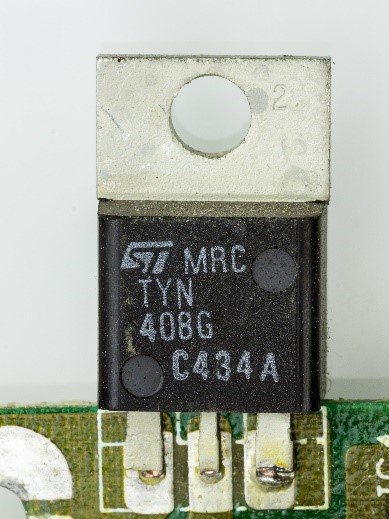
A typical Silicon Controlled Rectifier looks as follows:

Silicon control rectifier symbol
An Silicon Controlled Rectifier is denoted by the following symbol for all its uses in circuit diagrams and other representation purposes.

Types of Silicon Controlled Rectifier
The thyristors are categorized as follows:
- The Force-commutated thyristor.
- Line-commutated thyristor.
- The Gate-turn-off thyristor (GTO).
- Reverse-conducting thyristor (RCT),
- Static induction thyristor (SITH)
- Gate-assisted turn-off thyristor (GATT)
- Light activated silicon-controlled rectifier (LASCR).
- MOS turn-off (MTO) thyristors emitter turn-off (ETO) thyristors,
- Integrated gate-commutated thyristor (IGCT).
- MOS-controlled thyristor (MCTs).
Why SCR is called silicon controlled rectifier ?
- Generally, rectifiers can be classified as controlled rectifiers and uncontrolled rectifiers.
- Diodes come under the category of uncontrolled rectifiers as they conduct without any control, as long as the anode voltage is greater than cathode voltage (also called forward-bias condition)
- SCRs, on the other hand, are called controlled rectifiers as they conduct only when the gate terminal is triggered. Thus, by providing a triggering pulse to the gate, we can control the working of the thyristor, as long as it is in the forward bias condition
Thyristor vs SCR
SCRs and Thyristors are essentially the same and can be used interchangeably. In this article also, both the terms will denote the same device.
High Power Silicon Controlled Rectifier
SCRs are known for their high power-handling capability. Natural or line-commutated thyristors having rating of 6000V, 4500A are also available. On an application level, these are huge values and therein lies the importance of SCRs. SCRs can handle such huge amounts of voltages and currents without damaging itself. The characteristics of the SCRs ensures that they will always have important power electronic applications.
Operation of Silicon Controlled Rectifier
- An SCR can be ON state by forward-biasing the anode-cathode junction and applying a pulse of positive gate current for a short duration. Once the device begins to conduct, we can remove this gate pulse and the Silicon Controlled Rectifier is latched on, though it is not possible to turn off the SCR by any gate pulse.
- If the anode current attempts to go to -ve, on account of the circuit onto which the SCR is connected, SCR may turn-off and the current will be 0.
- In its OFF-state, the thyristor will halts a forward polarized voltage and will not be in conducting stage.
- The I-V characteristics of an SCR can be studied to understand these points in further detail.
It is interesting to note that an SCR can be used for both AC and DC, Once the conditions for turning on are met – forward bias voltage and positive gate pulse – it conducts all currents, regardless of whether it is AC or DC.
Silicon Controlled Rectifier Characteristics
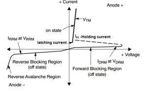
- Till the thyristor is triggered by a gate pulse, if a positive voltage is applied across the anode-cathode junction, the element is said to be in forward blocking state
- Once the device starts to conduct, the SCR is ON and can be said to be in forward conducting state
- If the voltage applied is negative, the device is said to be in reverse blocking region. In reverse blocking state, only a negligibly small leakage current flows in the thyristor.
- Once the negative voltage increases beyond a value called reverse breakdown voltage, the thyristor will start conducting in the negative direction. This voltage is also called peak reverse voltage. This is also called Zener breakdown or avalanche region.
We may study the following graph of Silicon Controlled Rectifier (SCR) characteristics to get a better idea.

Latching Current
Once the gate pulse is removed, the current flowing from anode to cathode must be more than a minimum vale, called latching current, to keep the device in the ON state. Otherwise, the device goes back it the blocking state.
Holding Current
- Small anode current is essential to keep the thyristor in the ON-state, That is known as holding current.
- The holding current is less than the latching current.
Silicon Controlled Rectifier Applications
Due to the controllable nature of the Silicon Controlled Rectifier and their availability in very wide range of voltage and current ratings, SCRs find their use in a wide variety of applications.
Some of them are
- Variable Speed Motor Drives
- AC motors, lights, welding machines
- Fault Current Limiters
- Circuit Breakers
- Light Dimmer Circuits
- Electric Fan Speed Control
- High Power Electrical Applications
Silicon Controlled Rectifier Dimmer
- As, SCR is a controllable device, it can be used in dimming circuits.
- The basic idea behind this process is that the point on the waveform where the device is turned on is changed. Essentially, it is also a form of phase control. It is also called forward phase dimming.
- Generally, sinusoidal supply is given to the lights. So, as opposed to turning on at the point of zero crossing, we turn on at different instants, thereby controlling the power.
- Some of the drawbacks of SCR Dimmer circuits are hum/noise, electrical noise(harmonics) and inefficiency.
SCR Heater Control
- The general idea behind working of SCR Heater is same as that of in SCR Dimmer, i.e we control the power given to resistor loads by changing the instant of turn-on.
- The SCR heater works by varying the time the electric heater is turned-on & therefore modulating the amount of heat supplied.
- The SCR control can deliver electrical power in mainly 2 ways, phase angle fired and zero voltage switched modes.
Phase Angle Fired Mode
In this mode, the control is such that a percentage of power is turned on in each cycle (i.e one cycle of an alternating current). This can give smooth & variable power delivery to the heaters. Essentially, the time instant at which a gate pulse is given to the SCR is varied. This is what the term “phase angle” in the title corresponds to.
Zero Voltage Switched
Here, the switches turn and off full cycles of the sinusoidal waveforms proportionately so that by varying the number of AC cycles, we can get the required power at the output.
SCR Power Controllers
- The principle behind SCR power controllers are basically what we have discussed before; control the flow of electricity(and hence power) from the supply to the heater.
- The find uses in industries and manufacturing processes for temperature regulation for different applications.
- It basically adjusts the firing angle(phase angle from zero-point crossing of sine wave to the instant where gate pulse is applied) to maintain a constant voltage output, which is set.
SCR Motor Controller
- SCRs can be employed to control the speed of a DC motor using the following electrical circuit.
- Two SCRs are used to convert the input AC voltage into a pulsating dc voltage.
- This pulsating dc voltage can be varied by controlling the output of the SCR rectifier circuit, which in turn is controlled by the timing of firing of gate pulses. Essentially, output voltage is varied.
- In this way, SCR can operate at different levels & apply various voltages to the motor armature, thereby controlling the speed of the DC motor. If the thyristor conductors for shorter durations, its output voltage(of the rectifier circuit) becomes lower, lower voltage is applied to the DC motor and therefore the speed of the DC motor is reduced.
SCR vs TRIAC
- The main difference between an SCR and a TRIAC is that SCR is a unidirectional device, which means it allows current flow in only one direction, whereas a TRIAC is a bidirectional device i.e it allows current flow in both the directions.
- For triggering an SCR, a positive gate pulse is required whereas most TRIACs can be triggered by applying either a negative or a positive voltage to the gate terminal.
- TRIACs are mainly used to control AC power
3 Phase SCR
- Three-phase SCRs are circuits in which SCRs are used in each phase leg i.e for the 3 phases. The functioning and application of the SCRs are same as before, with only difference being that they are used for 3-phase supplies now.
- As before, SCRs are used in two control modes, zero-crossing mode and phase angle control mode. Their working is same as that explained before
Frequently Asked Questions
Q. In an SCR silicon controlled rectifier why is the holding current less than the latching current ?
- Latching current, as defined before, is the minimum current that must be present at the point of gate pulse removal to maintain conduction, whereas Holding Current is the minimum current that is required to be maintained to keep the device in the ON state.
- The latching current limit is purposely kept greater than holding current so as to avoid misfiring of SCRs and provide smooth operation.
Q. How an SCR is triggered ?
Operation of Silicon Controlled Rectifier
Q. Why SCR is called a controlled rectifier ?
An SCR is called a controlled rectifier because as opposed to a diode, the turn-on time can be controlled for the device. Hence, the voltages at the out of the Silicon Controlled Rectifier are controllable depending on the instant of turn-on.
Q. What is SCR and its types?
Types of Silicon Controlled Rectifier
For more details on SCR, click here
For more articles, click here

The lambdageeksScience Core SME Team is a group of experienced subject matter experts from diverse scientific and technical fields including Physics, Chemistry, Technology,Electronics & Electrical Engineering, Automotive, Mechanical Engineering. Our team collaborates to create high-quality, well-researched articles on a wide range of science and technology topics for the lambdageeks.com website.
All Our Senior SME are having more than 7 Years of experience in the respective fields . They are either Working Industry Professionals or assocaited With different Universities. Refer Our Authors Page to get to know About our Core SMEs.