Points of Discussion: Microwave Resonators
- Introduction to Microwave Resonators
- Series Resonator Circuit
- Parallel Resonator Circuit
- Transmission Line Resonators
- Solved Mathematical Example of Microwave Resonators
Introduction to Microwave Resonators
Microwave resonators are one of the crucial elements in microwave communication circuit. They can create, filter out, and select frequencies in various applications, including oscillators, filters, frequency meters, and tuned oscillators.
Operations of microwave-resonators are very much like the resonators used in network-theory. We will discuss the series and parallel RLC resonant circuits at first. Then, we will find out various applications of resonators at microwave frequencies.
Know about Microwave Engineering and Its Overview. Click Here!
Series Resonator Circuit
A series resonator circuit is made by arranging a resistor, an inductor, and a capacitor in series connection with a voltage source. The circuit diagram of a series RLC is given below. It is one of the type of microwave resonators.
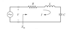
The input impedance of the circuit is given as Zin = R + jωL − j /ωC
The complex power from the resonator is given by Pin.
Pin = ½ VI* = ½ Zin | I|2 = ½ Zin | (V/Zin) |2
Or, Pin = ½ |I|2 (R + jωL − j /ωC)
The power by the resistor is: Ploss = ½ |I|2 R
The average magnetic energy stored by the inductor L is:
We = ¼ |Vc|2 C = ¼ |I|2 (1/ω2C)
Here, Vc is the voltage across the capacitor.
Now, complex power can be written as follow.
Pin = Ploss + 2 jω (Wm − We)
Also, the input impedance can be written as: Zin = 2Pin/ |I|2
Or, Zin = [Ploss + 2 jω (Wm − We)] / [½ |I|2]
In a circuit, resonance occurs when the stored average magnetic field and the electric charges are equal. That means, Wm = We. The input impedance at resonance is: Zin = Ploss / [½ |I|2] = R.
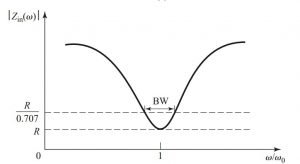
R is a pure real value.
At Wm = We, the resonance frequency ω0 can be written as ω 0 = 1/ √(LC)
Another critical parameter of the resonant circuit is the Q factor or quality factor. It is defined as the ratio of the average energy stored to the energy loss per second. Mathematically,
Q = ω * Average energy change
Or Q = ω *(Wm + We) / Ploss
Q is a parameter which gives us the loss. Higher Q value implies the lower loss of the circuit. Losses in a resonator may occur due to loss in conductors, dielectric loss, or radiation loss. An externally connected network may also introduce losses to the circuit. Each of the losses contributes to the lowering of the Q factor.
The Resonator’s Q is known as Unloaded q. It is given by Q0.
The unloaded Q or Q0 can be calculated from the previous equations of Q factor and Power loss.
Q0 = ω 0 2Wm / Ploss = w0L / R = 1/ w0Rc
From the above expression, we can say that the Q decreases with the increase of R.
We will now study the behaviour of the input impedance of the resonator circuit when it is near its resonance frequency. Let w = w0 + Δω, here Δω represents a minimal amount. Now, the input impedance can be written as:
Zin = R + jωL (1 − 1/ω2LC)
Or Zin = R + jωL ((ω2 – ω02)/ω2)
Now, ω20 = 1/LC and ω2 − ω20 = (ω − ω0) (ω + ω0) = Δω (2ω − Δω)2ω Δω
Zin ~ R + j2L Δω
Zin ~ R + j2RQ0L Δω / ω0
Now, the calculation for half-power fractional bandwidth of the resonator. Now, if the frequency becomes |Zin| 2 = 2R2, the resonance receives 50% of the total delivered power.
One more condition is such that when the Band Width value is in fraction, the value of Δω/ω0 becomes half of the Band Width.
|R + jRQ0(BW)| 2 = 2R2,
or BW = 1/Q0
Know about Transmission Lines and waveguides. Click Here!
Parallel Resonant Circuit
A parallel resonator circuit is made by arranging a resistor, an inductor, and a capacitor in parallel with a voltage source. The circuit diagram of a parallel RLC is given below. It is one of the type of microwave resonators.
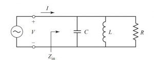
Zin gives the input impedance of the circuit.
Zin = [1/R + 1/jωL + jωC] −1
The complex power delivered from resonator is given as Pin.
Ploss = ½ VI* = ½ Zin | I|2 = ½ Zin | V|2 / Zin*
Or Pin = ½ |V|2 (1/R + j/wL – jωC)
The power from resistor R is Ploss.
Ploss = ½ |V|2 / R
Now, the Capacitor also stores the energy, it is given by –
We = ¼ |V|2C
The inductor also stores the magnetic energy, it is given by –
Wm = ¼ |IL|2 L = ¼ |V|2 (1/ ω2L)
IL is the current through the inductor. Now, the complex power can be written as: Pin = Ploss + + 2 jω (Wm − We)
The input impedance can also be written as: Zin = 2Pin/ |I|2 = (Ploss + 2 jω (Wm − We))/ ½ |I|2
In the series circuit, the resonance occurs at Wm = We. Then the input impedance at resonance is Zin = Ploss / ½ |I|2 = R
And the resonant frequency at Wm = We can be written as w0 = 1 / √ (LC)
It is same as the value of series resistance. Resonance for the parallel RLC circuit is known as an antiresonance.
The concept of unloaded Q, as discussed early, is also applicable here. The unloaded Q for the parallel RLC circuit is represented as Q0 = ω02Wm/ Ploss.
Or Q0 = R /ω0L = ω0RC
Now, at antiresonance, “We = Wm”, and the value of the Q factor decreases with the decrease in R’s value.
Again, for input impedance near resonance frequency consider ω = ω0 +Δω. Here, Δω is assumed as a small value. The input impedance is again rewritten as Zin.
Zin = [ 1/R + (1 – Δω / ω0) / jω0L + jω0C + jΔωC] -1
Or Zin = [ 1/R + j Δω / ω2L + jΔωC] – 1
Or Zin = [ 1/R + 2jΔωC]-1
Or Zin = R / (1 + 2jQ0Δω/ω0)
Since ω2 = 1/LC and R = infinite.
Zin = 1 / (j2C (ω – ω0))
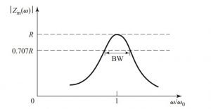
The half-power bandwidth edges occur at frequencies (Δω / ω0 = BW/2) such that, |Zin|2 = R2/ 2
Band Width = 1 / Q0.
Transmission Line Resonators
Almost always, the perfect lumped components can not deal in the range of microwave frequencies. That is why distributed elements are used at microwave frequency ranges. Let us discuss various parts of transmission lines. We will also take into consideration of the loss of transmission lines as we have to calculate the resonators’ Q value.
For Detail Analysis of Transmission Lines… Click Here!
Short circuited λ/2 Line
Let us take a transmission line which suffers loss and also it is short-circuited at one of its terminal.
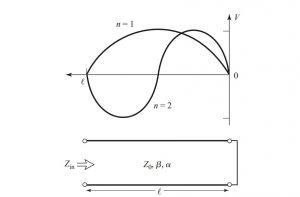
Let us assume the transmission line has a characteristic impedance of Z0, the propagation constant of β and attenuation constant is α.
We know that, at resonance, the resonant frequency is ω = ω0. The length of the line ‘l’ is λ/2.
The input impedance can be written as Zin = Z0 tanh (α + jβ)l
Simplifying the tangential hyperbolic function, we get Zin.
Zin = Z0 (tanh αl + j tan βl) / (1 + j tan βl tanh αl).
For a lossless line, we know that Zin = jZ0 tan βl if α = 0.
As discussed earlier, we will consider the loss. That I why, we will take,
αl << 1 and tanh αl = αl.
For a TEM line,
βl = ωl/ vp = ω0l/ vp + Δωl/ vp
vp is an important parameter which represents the transmission line’s phase velocity. L = λ/2 = πvp/ω0 for ω = ω0, we can write,
βl = π + Δωπ/ ω0
Then, tan βl = tan (π + ωπ/ ω0) = tan (ωπ/ ω0) = ωπ/ ω0
Finally, Zin = R + 2 jLω
At last, the value of resistance comes as: R = Z0αl
The value of inductance comes as : L = Z0π/ 2ω0
And, the value of Capacitance comes as : C = 1/ ω20L
The unloaded Q of this resonator is, Q0 = ω0L/ R = π/ 2αl = β/ 2α
Solved mathematical Example of Microwave Resonators
1. A λ/2 resonator is made up of copper coaxial line. Its inner radius is 1 mm, and the outer radius is 4mm. The value of the resonant frequency is given as 5 GHz. Comment on the calculated Q value of two coaxial line among which one is filled with air another filled with Teflon.
Solution:
a = 0.001, b = 0.004, η = 377 ohm
We know that the conductivity of the copper is 5.81 x 10⁷ S/m.
Thus, the surface resistivity at 5GHz = Rs.
Rs = root (ωµ0/ 2σ)
Or Rs = 1.84 x 10⁻² ohm
Air filled attenuation,
αc = Rs /2η ln b/a {1/ a + 1/ b}
Or αc = 0.22 Np/m.
For Teflon,
Epr = 2.08 and tan δ = 0.0004
αc = 0.032 Np/m.
There is no dielectric los due to air filled, But for Teflon-filled,
αd = k0 √epr/2 * tan δ
αd = 0.030 Np/m
So, Qair = 104.7 / 2 * 0.022 = 2380
Qtefflon = 104.7 * root(2.008) / 2 * 0.062 = 1218

Hi, I am Sudipta Roy. I have done B. Tech in Electronics. I am an electronics enthusiast and am currently devoted to the field of Electronics and Communications. I have a keen interest in exploring modern technologies such as AI & Machine Learning. My writings are devoted to providing accurate and updated data to all learners. Helping someone in gaining knowledge gives me immense pleasure.
Let’s connect through LinkedIn –