Contents: Moment Area Method and Macaulay’s Method
- Macaulay’s Method Definition
- Macaulay’s Method for slope and deflection
- Macaulay’s Method example 1: Slope and Deflection in a Simply supported Beam for Uniformly Distributed Load
- Macaulay’s Method example 2: Slope and Deflection in an Overhanging Beam
- Moment-Area Method
- Moment Area Theorem
- Example related to Moment Area Method
- Bending Moment by parts
- Applying Moment Area method on overhanging Beam with Uniformly distributed Loading for finding slope and deflection
- Maximum Deflection due to unsymmetrical Loading
- Q & As on Macaulay’s Method and Moment Area Method
Macaulay’s method
Mr W.H Macaulay devised Macaulay’s Method. Macaulay’s Method is very efficient for discontinuous loading conditions.
Macaulay’s Method for Slope and Deflection
Consider a small section of a Beam in which, at a particular section X, the shearing force is Q and the Bending Moment is M as shown below. At another section Y, distance ‘a’ along the Beam, a concentrated load F is applied which will change the Bending Moment for the points beyond Y.
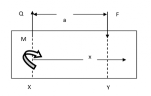
Between X and Y,
![Rendered by QuickLaTeX.com \\\\M=EI \\frac{d^2 y}{dx^2}=M+Qx……………[1]\\\\\\\\EI \\frac{dy}{dx}=Mx+Q\\frac{x^2}{2} +C_1……………[2]\\\\\\\\EIy=M \\frac{x^2}{2}+Q \\frac{x^3}{6}+C_1 x+C_2……………[3]](https://lambdageeks.com/wp-content/ql-cache/quicklatex.com-7a7924845c3cf36f0f2abd47deede5c3_l3.png)
And Beyond Y
![Rendered by QuickLaTeX.com M=EI \\frac{d^2 y}{dx^2}=M+Qx-F(x-a)…………… [4]\\\\\\\\EI \\frac{d y}{dx}=Mx+Q (x^2/2)-F (x^2/2)+Fax+C_3…………… [5]](https://lambdageeks.com/wp-content/ql-cache/quicklatex.com-f9e0c4066c5236e95b7fe913d583ce07_l3.png)
![]()
For the slope at Y, equating [5] and [2] we get,
![]()
But at Point Y, x = a
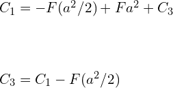
Substituting the above equation in [5]
![]()
![]()
Also, for the same deflection at Y equating (3) and (6), with (x=a) we get
![]()
On solving these equations and substituting value of C3
![]()
Substituting in equation [6] we get,
![]()
![]()
By further Investigating equations [4], [7] and [8] we can conclude that the Single Integration Method for obtaining Slope and deflection will still be applicable provided that the term F(x-a) is integrated with respect to (x-a) and not x. Also, the term W(x-a) is applicable only for (x>a) or when (x-a) is positive. Thus, these terms are called Macaulay terms. Macaulay terms should be integrated with respect to themselves and must be neglected when they are negative.
Thus, the generalized equation for the whole Beam becomes,
![]()
Macaulay’s Method example 1: Slope and Deflection in a Simply supported Beam for Uniformly Distributed Load
Consider a simply supported beam with uniformly distributed loading over the complete span. Let weight acting at distance a from End A and W2 acting at a distance b from end A.

The Bending Moment Equation for the above beam can be given by
![]()
The U.D.L applied over the complete beam doesn’t require any special treatment associated with the Macaulay’s brackets or Macaulay’s terms. Keep in mind that Macaulay’s terms are integrated with respect to themselves. For above case (x-a) if it comes out negative then it must be ignored. Substituting the end conditions will yield the values of constants of integration in the conventional way and hence the required value of slopes and deflection.

In This case the U.D.L starts at point B the bending moment equation is modified and the uniformly distributed load term becomes Macaulay’s Bracket terms.
The Bending Moment equation for the above case is given below
![]()
Integrating we get,
![]()
![]()
Macaulay’s Method example 2: Slope and Deflection in an Overhanging Beam
Given below is the overhanging beam in Fig. (a), we are need to calculate
(1) the equn for the elastic curve.
(2) the mid-values in-between the supports and at point E (indicate whether each is up or down).

To determine the bending moment for the above beam the equivalent loading is used, is given below as Figure (b). In order to use Macaulay’s Bracket in the Bending Moment equations, we are required to extend each distributed load to the right end of the beam. We extends the 800 N/m loadings to point E and eliminates the un-necessary portion by applying an equal and opposite loadings to C-E. The global expression for the bending moment represented by free-body diagram in figure(c).


Substituting M into the differential equation for the elastic curve,
![]()
Integrating it,
![]()
Again, Integrating it,
![]()
At Point A, the deflection is restricted due to simple support at A. Thus, at x = 0, y=0,

Again, at Point D the deflection is restricted due to simple support at D. at x = 6 m, y = 0,
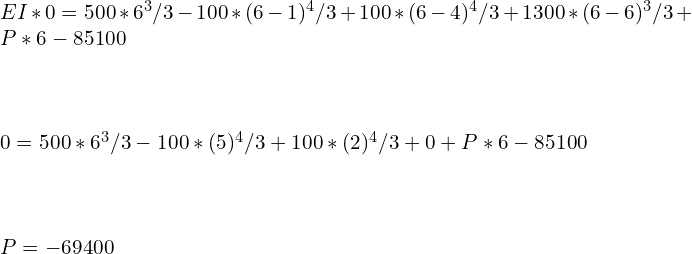
When we substitute the values for P and Q to Eq. (a), we get
![Rendered by QuickLaTeX.com EIy=500 x^3/3-100 (x-1)^4/3+100(x-4)^4/3 +1300 (x-6)^3/3-69400x-85100….[b]](https://lambdageeks.com/wp-content/ql-cache/quicklatex.com-72ead26f902dc74d0243c543f7c30743_l3.png)
This is the Generalized equation to find deflection over the complete span of overhanging Beam.
In order to find the deflection at a distance of 3 m from the left end A, Substitute the value of x =3 in Eq. (b),
The equation of elastic curve so obtained is given by,
![]()
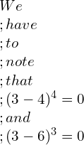
![]()
The negative sign of the value indicates that the deflection of the beam is downward direction in that region.
Now finding the Deflection at the extreme of the Beam i.e., at Point E
Put x = 8 m in eq. [b]
![]()
![]()
Again, the negative sign indicates the downward deflection.
Moment Area Method
In order to determine the slope or deflection of a beam at a specified location, the moment area method is considered most effective.
In this Moment Area Method, the bending moment’s integration is carried out indirectly, using the geometric properties of the area under the bending moment diagram, we assume that the deformation of Beam is below the elastic range and this results in small slopes and small displacements.
The First theorem of Moment Area method deals with slopes; the second theorem Moment Area method deals with deflections. These Two theorems form the basics of the Moment Area Method.
Moment Area Theorem
First – Moment Area Theorem
Consider a beam segment which is initially straight. The elastic curve AB for the segment taken into consideration is shown in fig (a). Consider two cross-sections of the beam at P and Q and rotate them through the angle dϴ relative to each other also separated by the distance dx.
Let’s assume the cross sections remain perpendicular to the axis of the beam.
dϴ = Difference in the slope of curve P and Q as depicted in Fig. (a).
From the given geometry, we see that dx = R dϴ, where R is the curvature radius of the deformed element’s elastic curve. Therefore, dϴ = dx/R, which upon using the moment-curvature relationship.
![Rendered by QuickLaTeX.com \\frac{1}{R}=\\frac{M}{EI} \\;becomes\\;d\\theta=\\frac{M}{EI}dx \\;\\;…………..[a]](https://lambdageeks.com/wp-content/ql-cache/quicklatex.com-d2952053580c71cb0ea3819c2185dca7_l3.png)
Integrating Eq.(a) over the segment AB yields
![Rendered by QuickLaTeX.com \\int_{B}^{A}d\\theta=\\int_{B}^{A}\\frac{M}{EI}dx\\;\\;……………..[b]](https://lambdageeks.com/wp-content/ql-cache/quicklatex.com-b374e8292a1c3064034cb1f695091e02_l3.png)
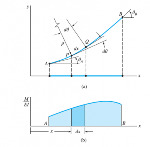
The left-hand side of Eq. (b) is the change in the slope between A and B. The right-hand side represents the area under the M/EI diagram between A and B, shown as the shaded area in Fig. (b). If we introduce the proper notation , Eq. (b) can be expressed in the form

This is the First theorem of Moment Area Method. The First theorem of Moment Area method deals with slopes
Second – Moment Area Theorem
Let t (B/A) be the vertical distance of point B from the tangent to the elastic curve at A. This distance is called the tangential deviation of B with respect to A. To calculate the tangential deviation, we first determine the contribution dt of the infinitesimal element PQ.
We then use integration for A to B dt = t (B/A) to add all the elements between A and B. As shown in the figure, dt is the vertical distance at B between the tangents drawn to the elastic curve at P and Q. Recalling that the slopes are very small, we obtain from geometry,
![]()
Where x’ is the horizontal distance of the element from B. Therefore, the tangential deviation is

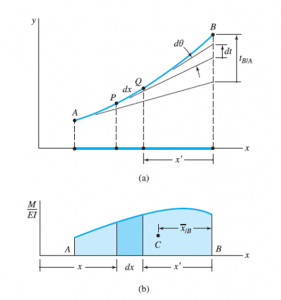
Putting value dϴ of in Equation [a] we get,
![Rendered by QuickLaTeX.com t_{B/A}=\\int_{B}^{A}\\frac{M}{EI}x'dx\\;\\;………………..[c]](https://lambdageeks.com/wp-content/ql-cache/quicklatex.com-eef0157da5362c825a210362d97093ae_l3.png)
The right-hand side of Eq. (c) represents the first moment of the shaded area of the M/(EI) diagram in Fig. (b) about point B. Denoting the distance between B and the centroid C of this area by , we can write Eq. (c) as
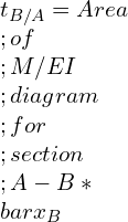


This is the second theorem of moment area method. The second theorem Moment Area method deals with deflections.
Bending Moment by parts
For studying Complex applications, the evaluation of the angle ϴ (B/A) and the tangential deviation can be simplified by independently evaluating the effect of each load acting on the beam. A separate Bending Moment diagram is drawn for each load, and the slope is obtained by algebraic summation of the areas under the various B.M.Ds. Similarly, the deflection is obtained by adding the first moment area about a vertical axis through point B. A bending-moment diagram is plotted in parts. When a bending-moment is drawn in parts, the various areas defined by the BMD consists of shapes, such as area under 2nd degree curves, cubic curves, rectangles, triangles, and parabolic curves, etc.
Steps to draw bending moments by parts
- Provide appropriate fixed support at a desired location. Simple supports are usually considered to be the best choice; however, another type of support is used depending upon the situation at hand.
- Calculate the support reactions and assume them to be applied loads.
- Draw a bending moment diagram for each load. Follow proper sign conventions while drawing bending moment diagram.
- The slope is obtained by algebraic summation of the areas under the various B.M.Ds.
- the deflection is obtained by adding the first moment area about a vertical axis through point B.
Applying Moment Area method on overhanging Beam with Uniformly distributed Loading for finding slope and deflection
Consider a Simply Supported overhanging beam with uniformly distributed loading from A to B and C to D as Shown below [ . Find slope and deflection by Using Moment Area method.]

From a free-body diagram of the beam, we determine the reactions and then draw the shear and bending-moment diagrams, as the flexural-rigidity of the beam is constant, to calculate (M/EI) diagram we need to divide each value of M by EI.
![]()
![]()

![]()
![]()
![]()
Drawing Shear Force and Bending Moment Diagram for the given beam
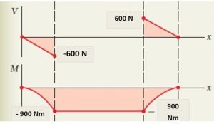
For Reference tangent: since the Beam is symmetric along with its loading with respect of Point C. The Tangent at C will act as a reference Tangent. From the diagram above

Thus, tangent at E can be given by,
![Rendered by QuickLaTeX.com \\theta_E=\\theta_c+\\theta_{E/C}=\\theta_{E/C} …………..[1]](https://lambdageeks.com/wp-content/ql-cache/quicklatex.com-3b283045ac009ea8ebe387e469643ea9_l3.png)
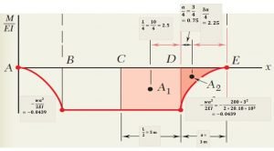
Slope at E: according to M/EI diagram and applying the First Moment area method as discussed above we get,
![]()
![]()
![]()
Similarly, for A2
![]()
![]()
![]()
From equation [1] we get,
![]()
![]()
Deflection at Point E can be calculated by using Second moment area method
![]()
![]()
![]()
Similarly,
![]()
![]()
![]()
But we know that

Maximum Deflection due to unsymmetrical Loading
When a simply supported beam carries an unsymmetrical load, the maximum deflection will not occur at the centre of beam and required to be identify the beam’s K-point where the tangent is horizontal in order to evaluate the maximum deflection in a beam.
- We start with finding Reference tangents at one of the supports of the beam. Let ϴa be the slope of the tangent at Support A.
- Compute the tangential deviation t of support B with respect to A.
- Divide the obtained quantity by the span L between the supports A and B.
- Since the slope ϴk=0, we must get,

Using the first moment-area theorem, we can conclusively predict that point K can be found by measuring an area A
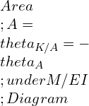
By Observation we conclude that the maximum deflection y (max) = the tangential deviation t of support A with respect to K (Fig. a) and we can determine y(max) by calculating the first moment area between Support A and point K with respect to the vertical axis.
Question and Answer of Macaulay’s Method and Moment Area Method
Q.1) Which method is useful in order to determine the slope and deflection at a point on a Beam?
Ans: Macaulay’s Method is very efficient for this case.
Q.2) What does Second Moment Area Method states?
Ans: The Second Moment Area method states that,” the moment of Bending moment diagram B.M.D between any two points on an elastic line divided by flexural rigidity (EI) is equal to the intercept taken on a vertical reference line of the tangent at these points about the reference line.”
Q.3) Calculate the deflection of the beam if the slope is 0.00835 radians. The distance from the free end to the center of gravity of bending moment is 5 m?
Ans: The deflection at any point on the elastic curve is equal to Mx/EI.
But we know that M/EI is slope equation = 0.00835 rad.
So, Deflection = slope × (The distance from the free end to the center of gravity of bending moment
Deflection = 0.00835*5 = 0.04175 m = 41.75 mm.
To know about Strength of material(click here)and Bending Moment Diagram Click here.

I am Hakimuddin Bawangaonwala , A Mechanical Design Engineer with Expertise in Mechanical Design and Development. I have Completed M. Tech in Design Engineering and has 2.5 years of Research Experience. Till now Published Two research papers on Hard Turning and Finite Element Analysis of Heat Treatment Fixtures. My Area of Interest is Machine Design, Strength of Material, Heat Transfer, Thermal Engineering etc. Proficient in CATIA and ANSYS Software for CAD and CAE. Apart from Research.