Cover Image Credit – Service Depicted: Air Force
Camera Operator: SSGT LOUIS COMEGER, Hammer Ace SATCOM Antenna, marked as public domain, more details on Wikimedia Commons
Points of Discussions
- Introduction
- Geometrical Analysis and Configurations
- Operational Modes
- Normal Mode
- Axial Mode
- Helical antenna design
- Helical antenna applications
Introduction to Helical Antenna
To define a helical antenna, we must know the correct definition of the antenna previously. As per to IEEE standard definitions of antennas or radiators,
“An antenna is a medium for transmitting and receiving radio waves”.
There are several adaptations of antennas. Some of them are – dipole antennas, horn antennas, log-periodic antennas, patch antennas, broadband antennas etc.

“Helical Beam Antennas, 1951” (CC BY-NC-ND 2.0) by NASAJPL
The helical antennas or helix antennas are one of the categories of broadband antennas. It is one of the most straightforward, primary and realistic antennas with a helical structure, made up of conducting wire-wound.
What is a horn antenna? Explore here!
Geometrical analysis and configuration
Helical antennas or helix antennas generally come with a ground plane which has the ability to accept distinct forms. To establish a typical helix connection with the ground plane, the ground plane’s diameter should be minimum of 3*λ/4. Although, the plane may be transfused into a cylindrical shaped crater. At the feed point, the transmission lines meet with the antenna.

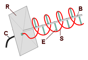
The geometrical description of a helix antenna typically consists of N number of turns, the diameter D and the distance between two helical loop S.
The whole length is given by –> L = N S.
The conductive wire’s whole length is given by –> Ln = N L0 (It carries the current primarily obviously!)
Or, Ln = N √ (C2 + S2); L0 = √ (C2 + S2)
L0 represents the dimension of the wire between two helical loops. It actually gives the length.
C represents the whole circumference of a spiral loop, and it is given by -> π D.
There is another spiral or helix antenna’s parameter, which is also very important. It is represented by the Greek alphabet alpha(α) and termed as ‘pitch angle’. This angle is generally the measurement of the line’s angle – normal to the helix wire and a steep ground to the helix axis. The mathematical expression is given below.
α = tan-1 (S/C)
or, α = tan-1 (S/ π D)
By carefully observing the equation, it can be concluded that when the angle tends to 0 degrees, the winding gets trampled; as a result, the helix antenna gets reduced and becomes similar to a simple loop antenna. Again, when the angle becomes 90 degrees, the antenna becomes a linear wire. When the angle is less than 90 degrees and greater than 0 degrees, then a practical helix has a finite value of circumference.
The architectural parameters can change the radiation properties of the helix antennas. Controlling the geometrical parameters will vary the radiation properties associated with the wavelength. The input impedance has a relation with the pitch angle and conducting wire’s size, as a change in pitch angle values, and the size of the wire will change the input impedance values.
Helical antenna typically shows elliptical polarization, although they can be designed to show circular and linear polarization.
Operational Modes
Helix antennas have the capability to function in many types of operational modes. There are two significant and essential operational modes that we will discuss in detail in the latter part of this article. The two modes are –
The three-dimensional figures of both the types of mode of operations are given below.

As we can see in the standard figure, it has a maximum in an imaginary plane which is normal to the axis, and its null is along the axis. The power pattern has a close similarity to the shape of the circular loop.
Now, the maximum is along the helix’s length for the end-fire mode, and the power pattern is similar to the end-fire array. That is why the mode is named as ‘End Fire Mode’.
The axial mode of operation has more preference over the standard mode of operation because it is more realistic or practical, has better efficiency and can show circular polarization with a broader bandwidth. An elliptically polarized antenna can be described as the summation of the two extraneous lined mechanisms in phase-time quadrature.
What does a transmission line do? Explore!
Normal Mode of Helix Antennas
As discussed previously, the antenna’s helical mode has its maximum radiation is directed to a plane normal to the helix axis, and the null radiation is along its axis. The normal mode of operation of helix antenna or broadside mode operation is achievable by comparing the wavelength, that is N L0 << λ0.
The helix architecture comes down to a loop of a diameter D as the pitch angle comes to 0 to a lined wire with a length of S while approaching to 90 degrees. Nos, as the helix’s geometry, became a loop and a dipole, the far-field radiation in this mode of operation can be represented respectively by Eϕ and Eϴ components of the dipole and the spiral loop.
The helix can be described as N number of small loops and the same number of small dipoles. They are linked with each other in a series manner. The arenas are calculated by using the superposition of the other fields from the rudimentary parts. The loop’s axes and the dipole’s axes coincide with the helix’s axis.
As this model has small dimensions, the current is assumed to be constant. Its operation can be defined by the summation of the fields radiated by a smaller-loops, having a diameter of D and a short dipole having a length of S.
The far-field electric field is given as –
Eϴ = j * η * k * I0 * S * e-jkr Sinϴ / 4πr
The Eϕ part is given by –
Eϕ = η* k2 * (D/2)2 * I0 * e-jkr Sinϴ /4r
The ratio of Eϴ and Eϕ gives the axial ratio. The mathematical expression is given below.
AR = | Eϴ | / | Eϕ |
Or, AR = 4S / πkD2
Or, AR = 2λS/ (πD)2
The pitch angle is given as – α = tan-1 (π D/2λ0)
Axial Mode of operation for Helical Antenna
The axial mode of operation has more preference over the standard mode of operation because it is more realistic or practical, has better efficiency and can show circular polarization with a broader bandwidth.
This mode is achieved by setting up large S and D. There are some requirements for achieving circular polarization. The range of the circumference of the helix should be in the below-given range.
4/3 > λ0/C > ¾
The pitch angle also has a limited range. The range of the pitch angle is given below.
12o ≤ α ≤ 14o
The terminal impedance range for this mode of operation is between one hundred ohms to two hundred ohms.
The following mathematical operation calculates the gain. For the following equation, S gives the distance between two turns, and N represents the total number of turns in a helical antenna.
G = 15 (C / λ) 2 * (NS / λ)
The half-power bandwidth of helical antenna for this mode of operation is given by following mathematical expression.
HPBW = 52 / [ (C/ λ) * √ {(NS / λ)}]
The full null bandwidth of helical antenna for this mode of operation is given by following mathematical expression.
FNBW = 115 λ3/2 / C * √ (NS)
Check out the radiation pattern of Yagi Uda Antenna!
Helical Antenna Design
- The input impedance is represented as ‘R’. The mathematical equation for ‘R’ is – R = 140 (C / λ0).
- The half-power bandwidth of helical antenna for this mode of operation is given by following mathematical expression. It has the accuracy of around plus-minus twenty percent. It is a measurement of angle and has a unit in degrees.
HPBW = 52 λ3/2 / C * √ (NS)
- The full null bandwidth of helical antenna for this mode of operation is given by following mathematical expression. It represents the measure of beamwidth among the Nulls. It has also unit in degrees.
FNBW = 115 λ3/2 / C * √ (NS)
- D0 represents the directivity of the antenna. The mathematical equation is –
D0 = 15 * N * C2S / λ03
- The following mathematical term gives the Axial Ratio or the AR.
AR = 2N+1 / 2N
- The following expressions give the generalized far-field pattern.
E = sin (π/ 2N) cosϴ sin [ (N/2) * Ψ] / sin (Ψ /2)
Ψ is given by another mathematical equation, and that is further given as Ψ = k0[S * cos ϴ – (L0/p)]
The value of ‘p’ for general end-fire array is
p = (L0/ λ0) * (S/ λ0 + 1)
The value of ‘p’ for Hansen-woodyard end-fire radiation is
p = (L0/ λ0) * [S/ λ0 + {(2N+1)/2N)}]
Helical Antenna Applications
The helical antenna has several applications in modern communication technologies. It has some unique applications because of its design and radiation patterns. Some of the spiral antenna applications are listed below.

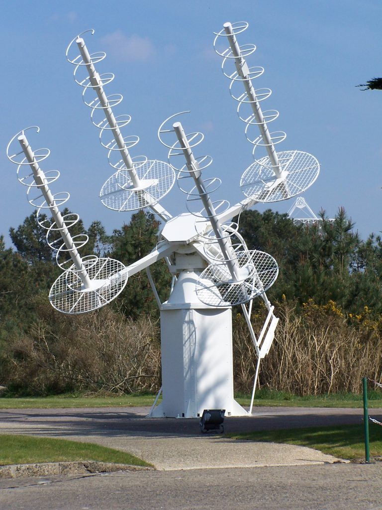
A satellite tracking helical antenna,
Image credit – Kingbastard, Traqueur acquisition, CC BY-SA 3.0
- Helical antennas are efficient in radiating very high-frequency range signals.

- Helical antennas are often used for space communications and satellites communications.
- Communications between two planets are possible because of these types of antennas.

Hi, I am Sudipta Roy. I have done B. Tech in Electronics. I am an electronics enthusiast and am currently devoted to the field of Electronics and Communications. I have a keen interest in exploring modern technologies such as AI & Machine Learning. My writings are devoted to providing accurate and updated data to all learners. Helping someone in gaining knowledge gives me immense pleasure.
Let’s connect through LinkedIn –