Any circuit can be designed with a parallel or series combination of different circuit elements. Any circuit element that has two terminals can form a parallel topology.
This article has described the parallel circuit function and its essential characteristics when different circuit elements are connected in parallel combinations.
Parallel Circuit Definition
Parallel circuit combination is one of the basic (or fundamental) electric circuit combination.
Parallel circuit combination is when one terminal of more than one circuit element is connected to one node of a circuit, and another terminal of the circuit element is connected to another node resulting in more than one path for current to flow.

Parallel Circuit Function:
Some characteristics of the basic (or elementary) parallel circuit:
- The voltage (or potential drop) across each path in parallel combination is identical
- The current through each part in parallel combination depends on the overall impedance or resistance across the path or branch of the circuit.
- The total current in the overall circuit is equal to the summation of current across each discrete path in a parallel combination.
- When more than one resistor, inductor, capacitor, and current source are linked in parallel combinations, that can be replaced by a one equivalent value of resistor, inductor, capacitor, and current source, respectively.
- The circuit is also a current divider circuit as the overall current throughout the circuit gets divided in all the paths in parallel combinations.
- The total(or over all) power dissipated in a parallel combination is equal to the summation of solitary power dissipated by every circuit element in a parallel circuit.
Voltage in a Parallel Circuit
The overall voltage of a parallel circuit has the same magnitude as the voltage across each branch or part of the circuit is constant.
So, if there is ‘n’ number of branches of path In The parallel circuit and V1, V2, V3, ….. Vn, is the individual voyage across each component of the parallel combination. then:
V1 = V2 = V3 …… = Vn
Current in a Parallel Circuit
In parallel circuit combination, the overall circuit current is split into different branches or paths of a parallel circuit. The highest current will be flowing through the branch, which has the overall lowest impedance or resistance.
Suppose if there are ‘n’ number of branches or paths in the parallel circuit and I1, I2, I3 ….. In, is the individual current across each branch in a parallel combination, and ‘I’ is the overall circuit current then:
I = I1 + I2 + I3 ….. + In
As known, the total current in a circuit must remain constant as neither charge is created or lost in the circuitry, so the total current passing in parallel branches will always be the same as the current before the junction.
Parallel Circuit Working
When a potential drop is measured between two points or the circuit node, the voltage across each path is identical when the path is connected between two nodes in a parallel combination.
In a parallel circuit, the current can take different paths with different magnitude to flow. That’s why the current throughout the parallel circuit cannot be constant as the voltage drops across each path or branch are constant.
The circuit current distributes itself across each branch or path in such a way that the current is inversely proportional to overall path or branch resistance or impedance, resulting in the current will be most significant in the part where resistance or impedance is least.
With Kirchhoff’s circuit law, Ohm’s law, or other circuit analysis methods, the voltage drop in a parallel circuit and current through any branch in parallel circuit combination can be calculated.
Parallel Circuit Configuration
Any parallel circuit can be a combination of Basic circuit elements such as resistor, capacitor, inductor, diode, etc.
Let’s take a circuit of parallel configuration as given below:

In the above parallel circuit combination, all the circuit element resistor, capacitor, diode, inductor are connected in parallel with each other as each terminal of all these circuit elements is connected between two nodes of the circuit.
Parallel Circuit Formula
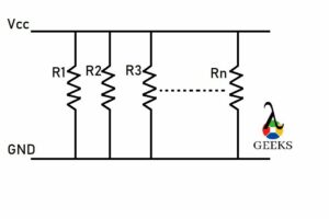
For Parallel Resistance
To calculate the total or overall resistance in parallel circuit combination of ‘n’ number of resistors, use formula:

Where Re -> equivalent resistance or total resistance of the parallel circuit combination.
R1, R2, R3 … Rn -> are the resistance of the individual resistors in a parallel circuit combination of ‘n’ number resistors.
For Parallel Capacitors
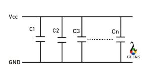
To calculate the total or overall capacitance of a parallel circuit combination of ‘n’ number of capacitors, use the formula:
Ct = C1 + C2+ C3 …..+ Cn
where Ct -> equivalent capacitance for the total capacitance of the parallel capacitor combination.
C1, C2, C3 … Cn is the capacitance of the individual capacitor in the parallel combination of the ‘n’ number of capacitors
For Parallel Inductors
To calculate the total or overall inductance in parallel circuit combination of ‘n’ number of inductors use the formula:

Where Le -> equivalent inductance or total inductance of the parallel combination.
L1, L2, L3 … Ln is the inductance of the individual inductor in the parallel combination of the ‘n’ number of inductors.

Parallel Circuit Advantages
let’s see why parallel circuit are in use? and what are the bonus of using any parallel circuitry:
- In parallel, circuit appliances are rated for the same (or identical) voltage, but different powers can be linked.
- Appliances and devices can be connected or disconnected from the circuit without affecting any other part of the circuitry.
- Every circuit element connected across each branch in parallel combination voltage is identical.
- If any fault or break occurs in any branch of the parallel circuit combination, it will not affect other branches of the circuitry.
- The current source can be linked in parallel combination, where the value of the current source linked in parallel combination can be identical or different from each other.
Parallel Circuit Disadvantages
As we already discussed about the bonus of parallel circuitry, now we are going to see the drawback of any parallel circuit:
- Voltage in the parallel circuit cannot be increased without decreasing the impedance or resistance of the overall parallel combination.
- In a parallel circuit, the current gets diverged into multiple branches. More than one current path is generated from numerous sources flowing into a single output or one source flowing into more than one output so that the parallel circuit can lead to Complex circuit design.
- In parallel combination, a more considerable length of wire is required.
- Parallel circuit combinations cannot be used where the constant current is required throughout .
- Voltage sources of unequal magnitude cannot be connected in parallel circuit combination if connected, and then it can generate a short circuit, vibration, cascade tripping, etc.
FAQ:
Why are circuits wired in parallel?
Parallel circuit combination has a different application which is used in various ways.
In parallel circuit combinations, devices with the same voltage rating can be connected. Connecting and disconnecting any devices from the circuit will not affect other device performance; any fault or break-in of any branch will not affect the other components of the circuit.
What happens to resistor in a parallel circuit?
In a parallel resistor circuit combination, several different resistors can be linked in parallel, and each resistor will have the identical voltage across it.
When resistors are linked in parallel than with the greater number of resistors in parallel circuit combination, the altogether resistance of the circuit decreases.
Why is voltage same in parallel circuit?
In parallel circuit combination, the voltage across each branch or path of the circuit is identical.
In an ideal parallel circuit combination, all the circuit elements connected in parallel combination are connected between two nodes of a circuit. That is why the voltage is the same in a parallel circuit.
Is current the same in parallel?
The parallel circuit combination current has several paths in which it can flow.
The current through each part depends on the overall resistance or impedance of the path. With different resistance or impedance values across the different ways of the parallel circuit, combination currents may vary from one path to another passage of the parallel circuit combination.
What is the main disadvantages of parallel circuits?
There are several advantages and disadvantages of any circuit combination.
The voltage in a parallel circuit combination cannot be increased without decreasing the overall impedance or resistance of the combination. The wiring requisite in a parallel circuit is more than that of a series circuit; altogether, constant current throughout the circuit cannot be obtained from a parallel circuit.

