How Are Analog Signals Converted to Digital: A Comprehensive Guide

how are analog signals converted to digital a comprehensive guide

Analog signals are continuous signals that can take on any value within a range, while digital signals are discrete signals that can only take on specific, distinct values. Converting analog signals to digital signals, also known as analog-to-digital conversion (ADC), is a crucial process in many electronic systems. This comprehensive guide will delve into the … Read more

Where Do the Effects of an LPF Appear in the Frequency Spectrum?

where do the effects of an lpf appear in the frequency spectrum

The effects of a Low Pass Filter (LPF) appear in the frequency spectrum by reducing the intensity of signal frequencies above a certain threshold, allowing only the lower frequencies to pass through. This is demonstrated in the frequency response of a low pass filter, which shows how much the filter attenuates higher frequencies relative to … Read more

Universal Gate NAND and NOR: A Comprehensive Guide for Electronics Students

universal gate nand and nor

Summary Universal gates, specifically NAND and NOR gates, are the fundamental building blocks of digital circuits. These gates can be used to implement any other logic gate, making them highly versatile and essential in the field of electronics. This comprehensive guide will delve into the technical details, practical applications, and implementation strategies of NAND and … Read more

Mastering Metastability: Navigating the Challenges of Unstable Systems

what is metastability and why is it a concern exploring the challenges of unstable systems

Metastability is a complex phenomenon that poses significant challenges in both electronic systems and human movement. This comprehensive guide delves into the intricacies of metastability, exploring its causes, consequences, and strategies for mitigating its impact. Whether you’re an electronics engineer or a biomechanics enthusiast, this article will equip you with the knowledge to navigate the … Read more

Crankshaft Position Sensor Diagram: Detailed Insights

Crankshaft sensor 296x300 1

Crankshaft Position Sensor as the name indicates it is a type of sensing device. In this article we will discuss about Crankshaft Position Sensor Diagram.

Crankshaft Position Sensor Diagram has importance in both petrol and diesel engines because Crankshaft Position Sensor is an electronic device most widely used to detect ignition timing and engine RPM. This diagram helps in proper installation of the sensor.

To maintain the efficiency of a car’s engine it is necessary to maintain a suggested speed by all the internal parts. To make it possible the crankshaft position sensor must senses the precise position of the crankshaft. In automobile engineering Crankshaft Position Sensor is commonly abbreviated as CKP.

What is a Crankshaft Position Sensor?

The main function of a crankshaft position sensor is to investigate the position or rotational speed of the crankshaft in both petrol and diesel engines.

Crankshaft Position Sensors perform multiple activities, mainly it monitors the exact movement of the crankshaft and in turn we get other related important parameters like engine speed and ignition and fuel injection timing. Engine speed in RPM can also measured by using these sensors.

Depending on model, year of manufacturing and making the crankshaft position sensor wiring diagram are quite different from each other. Generally the manufacturer of these sensors decide the wiring diagram as per the requirement and demand in the market.

For different brands of Position Sensors the color of wires are different and color codes also vary as per the brands. Before wiring a specific make and model of sensor one has to check the car’s owner manual.

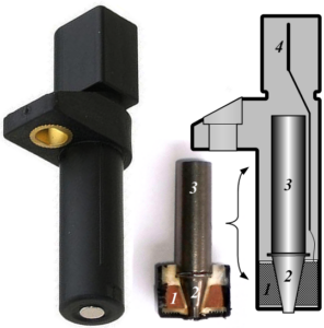
crankshaft position sensor diagram
Crankshaft Position Sensor; Image credit: Wikipedia

Crankshaft Position Sensor Working

CKP is placed very near to the reluctor ring so that the teeth attached to it rotates close to the sensor tip. There is a gap maintained in between the reluctor teeth to give the ECU a reference point to the crankshaft rotation or position.

With the rotation of the crankshaft, a pulsed voltage signal is produced by the sensor, each pulse is corresponding to the teeth of the reluctor ring.

Using these signals the engine control unit to determine the exact timing of fuel injection or spark ignition and in which cylinder. If anyone of the cylinders misfires, the signal from the cylinder also indicates it. Whenever the signal from the sensor is missing the control unit stops spark and fuel injector won’t operate.
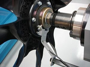
Clutch with Hall Effect sensor
Engine fan with Hall effect sensor; Image Credit: Wikipedia

2 Wire Crank Sensor Wiring Diagram

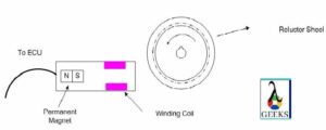
The two-wire crankshaft position sensor consists of a Signal Wire, a Ground Wire and an ECU.

In 2 wire crank sensor, the function of the signal wire to send the voltage from position sensor to the ECU(Electronic Control Unit). The ground wire is required to complete the electric circuit. Both of these wires are connected to ECU.
2 wire
2 Wire Crank Sensor

2 wire crank sensor is an inductive type sensor which consists of sensor magnet and winding coil and a toothed wheel. As the reluctor ring or the toothed wheel comes closer to the crank sensor, the magnetic field fluctuates as a result voltage is produced in the wiring coil. This voltage or signal is sent to the ECU which will calculate the position of the crankshaft.

Inductive type position sensors does not require any external voltage source wire to energize it. When any item comes near to it produces the voltage itself. The Crankshaft Position Sensor Diagram for 2Wire is given below:
2W
2 Wire Crankshaft Position Sensor Diagram

Crankshaft Position Sensor diagrams are different depending on the type and model of the sensors.

3 Wire Crank Sensor Wiring Diagram

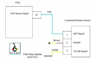
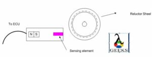
3 wire crank sensor mainly consists of 3 wires, reference voltage, signal and ground wire. This type of sensors are classified as hall effect type sensor.

A 3 wire crank sensor has a magnet and a steel type material like germanium and a transistor. As soon as the toothed wheel comes near the sensor, the magnetic flux of the magnet in the sensor changes and as a result voltage is produced. This voltage is ampliphied by the transistor and sent to the car computer.
3 wire
3 Wire Crank Sensor

Additional external voltage is required in 3 wire crank sensor. This type of sensor has an integrated circuit and an outside power source is necessary to work which amplifies the voltage.

That’s why it has three wires, earth, voltage, and a signal wire. The Crankshaft Position Sensor Diagram for 3 Wire is given below:

3 W
3 Wire Crankshaft Position Sensor Diagram

Crankshaft Motion

A crankshaft plays an important role inside an IC Engine by transforming the reciprocating movement of the piston into rotary motion.

In a reciprocating engine, using a connecting rod piston and crankshaft are connected so that reciprocating motion of the piston can be delivered to the crankshaft. After receiving this reciprocating motion from piston via connecting rod, crankshaft changes it into rotary motion.

Crankshaft is essential to get rotary motion for the flywheel which ultimately responsible for moving the car wheels.

The Logic Gates Role in Gaming Consoles: A Comprehensive Guide

the logic gates role in gaming consoles

The logic gates play a crucial role in the functioning of gaming consoles by processing and manipulating digital signals, enabling the performance of complex tasks. These fundamental building blocks of digital electronics are essential for creating the intricate digital circuits that power the advanced features and capabilities of modern gaming consoles. Understanding Logic Gates Logic … Read more

Does Filtering a Signal Impact its Frequency Spectrum?

does filtering a signal impact its frequency spectrum

Filtering a signal has a significant impact on its frequency spectrum, which is a crucial concept in various fields of electronics and signal processing. This comprehensive guide will delve into the technical specifications and details that electronics students need to understand the impact of filtering on a signal’s frequency spectrum. Filter Types and Their Impact … Read more

Designing an Ideal LPF with a Brick Wall Response: Exploring the Limits of Low Pass Filter Design

is it possible to design an ideal lpf with a brick wall response exploring the limits of low pass filter design

Designing an ideal low-pass filter (LPF) with a brick wall response is a challenging task in the field of signal processing and electronics. While it is theoretically possible, the practical limitations of real-world components and signal processing techniques make it a complex endeavor. In this comprehensive guide, we will delve into the intricacies of designing … Read more

How Can the Capacitance of a Varactor Diode be Changed: A Comprehensive Guide

how can the capacitance of a varactor diode be changed a comprehensive guide

The capacitance of a varactor diode, also known as a voltage-variable capacitor (VVC), can be precisely controlled by adjusting the reverse bias voltage applied to the device. This ability to dynamically change the capacitance makes varactor diodes an essential component in various electronic circuits, including tunable filters, voltage-controlled oscillators (VCOs), and phase-locked loops (PLLs). In … Read more

Can an HPF be Constructed Using Only R and C?

can an hpf be constructed using only r and c 1

An HPF (High-Pass Filter) is an electronic circuit that allows high-frequency signals to pass through while blocking or attenuating low-frequency signals. It is possible to construct an HPF using only resistors (R) and capacitors (C) by taking advantage of the frequency-dependent characteristics of these components. Understanding the Fundamental Principle of an RC HPF The fundamental … Read more