When Should an Amplifier be Replaced or Repaired: A Comprehensive Guide

when should an amplifier be replaced or repaired a comprehensive guide

When determining whether to replace or repair an amplifier, there are several measurable and quantifiable factors to consider. This comprehensive guide will provide you with the necessary information to make an informed decision on when to replace or repair your amplifier. Amplifier Lifespan and Repair Frequency Amplifiers typically have a lifespan of 10-15 years, depending … Read more

High Frequency Logic Challenges: A Comprehensive Guide for Electronics Engineers

high frequency logic challenges

High-frequency logic challenges are a critical aspect of electronics engineering, particularly in the design and implementation of high-speed digital circuits. These challenges are characterized by the rapid transition of signals, which can lead to signal integrity issues such as crosstalk, reflection, and attenuation. To address these challenges, it is essential to quantify and measure various … Read more

Does the Quality Factor Q Affect the Transition Region of a High-Pass Filter?

does the quality factor q affect the transition region of an hpf

The quality factor (Q-factor) is a crucial parameter that significantly impacts the performance and characteristics of high-pass filters (HPFs). In the context of HPFs, the Q-factor directly affects the transition region, which is the area between the passband and the stopband where the filter transitions from allowing signals to pass through to blocking them. Understanding … Read more

Mastering the Art of Finding Parallel Resistance: A Comprehensive Guide

how to find parallel resistance

In the world of electrical circuits, understanding the concept of parallel resistance is crucial for designing, analyzing, and troubleshooting various electronic systems. This comprehensive guide will delve into the intricacies of finding parallel resistance, providing you with a step-by-step approach and a wealth of technical details to ensure you become a proficient practitioner in this field.

Understanding Parallel Resistance

Parallel resistance is a fundamental concept in electrical engineering, where multiple resistors are connected in a parallel configuration. In a parallel circuit, the current has multiple paths to flow through, and the total resistance of the circuit is always less than the resistance of the individual components.

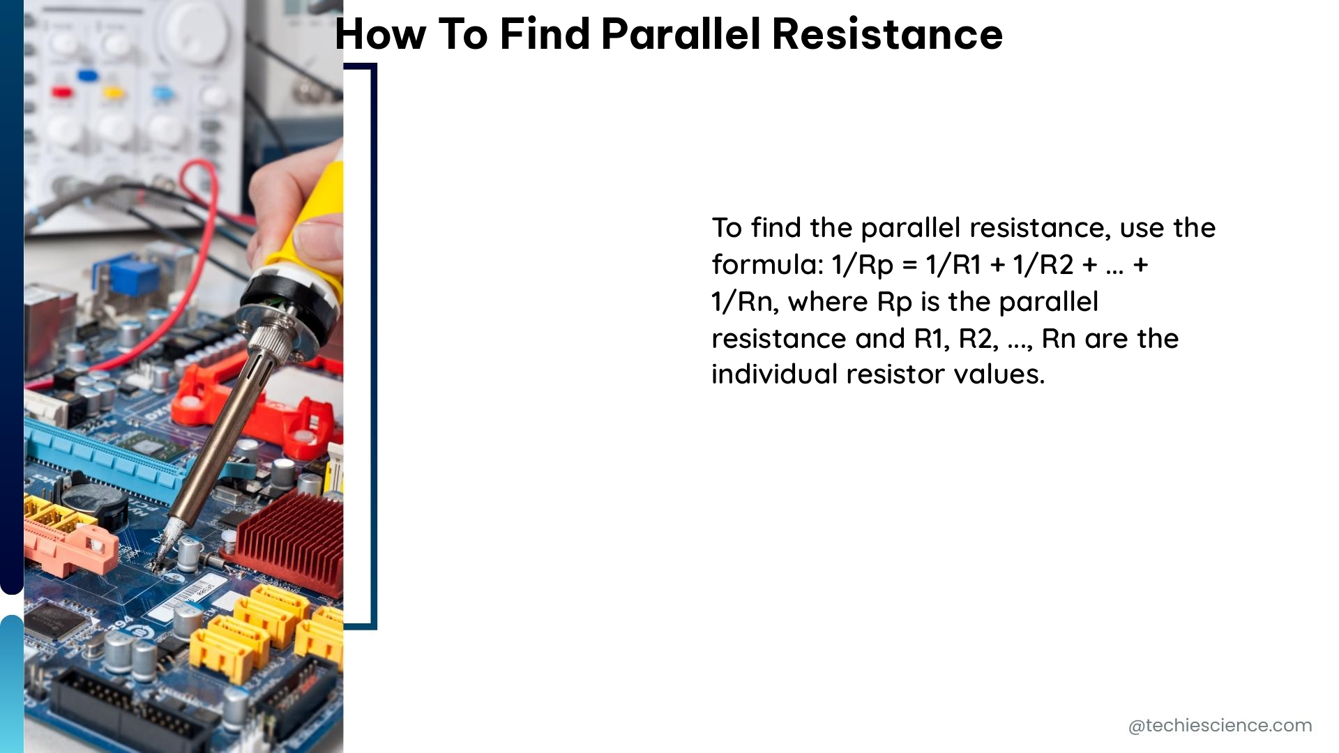
The formula to calculate the equivalent resistance (Req) of a parallel circuit is:

1/Req = 1/R1 + 1/R2 + 1/R3 + … + 1/Rn

Where R1, R2, R3, …, Rn are the individual resistor values in the parallel circuit.

Calculating Parallel Resistance: Step-by-Step Approach
how to find parallel resistance

To find the parallel resistance of a circuit, follow these steps:

Step 1: Identify the Resistors in Parallel

The first step is to identify the resistors that are connected in parallel. This can be done by carefully examining the circuit diagram or the physical layout of the components.

Step 2: Determine the Individual Resistor Values

Once you have identified the resistors in parallel, you need to determine the individual resistance values. This information can be obtained from the circuit diagram, component datasheets, or by directly measuring the resistors using a multimeter.

Step 3: Apply the Parallel Resistance Formula

With the individual resistor values, you can now apply the parallel resistance formula to calculate the equivalent resistance of the circuit:

1/Req = 1/R1 + 1/R2 + 1/R3 + … + 1/Rn

Step 4: Simplify the Calculation

After applying the formula, you may need to simplify the calculation to arrive at the final equivalent resistance value. This may involve performing mathematical operations such as addition, subtraction, multiplication, and division.

Step 5: Verify the Result

Once you have calculated the equivalent resistance, it’s important to verify the result. You can do this by checking the calculated value against the expected or measured resistance of the circuit.

Examples and Case Studies

Let’s explore some practical examples to solidify your understanding of finding parallel resistance.

Example 1: Two Resistors in Parallel

Suppose you have two resistors, R1 = 20 Ω and R2 = 30 Ω, connected in parallel. To find the equivalent resistance, we can use the formula:

1/Req = 1/R1 + 1/R2
1/Req = 1/20 + 1/30
1/Req = 3/60 + 2/60
1/Req = 5/60
Req = 60/5 Ω
Req = 12 Ω

Therefore, the equivalent resistance of the parallel circuit with two resistors is 12 Ω.

Example 2: Three Resistors in Parallel

Now, let’s consider a parallel circuit with three resistors: R1 = 20 Ω, R2 = 30 Ω, and R3 = 30 Ω. To find the equivalent resistance, we can use the formula:

1/Req = 1/R1 + 1/R2 + 1/R3
1/Req = 1/20 + 1/30 + 1/30
1/Req = 3/60 + 2/60 + 2/60
1/Req = 7/60
Req = 60/7 Ω
Req ≈ 8.57 Ω

Therefore, the equivalent resistance of the parallel circuit with three resistors is approximately 8.57 Ω.

Example 3: Parallel Resistance with Varying Resistor Values

In this example, let’s consider a parallel circuit with four resistors: R1 = 10 Ω, R2 = 20 Ω, R3 = 30 Ω, and R4 = 40 Ω. To find the equivalent resistance, we can use the formula:

1/Req = 1/R1 + 1/R2 + 1/R3 + 1/R4
1/Req = 1/10 + 1/20 + 1/30 + 1/40
1/Req = 4/60 + 3/60 + 2/60 + 1.5/60
1/Req = 10.5/60
Req = 60/10.5 Ω
Req ≈ 5.71 Ω

Therefore, the equivalent resistance of the parallel circuit with four resistors of varying values is approximately 5.71 Ω.

Practical Applications and Considerations

Parallel resistance is widely used in various electronic circuits and systems, including:

  1. Power Supply Circuits: Parallel resistors are often used in power supply circuits to distribute the current load and ensure efficient power distribution.
  2. Sensor Networks: In sensor networks, parallel resistors are used to create voltage divider circuits for signal conditioning and processing.
  3. Lighting Systems: Parallel resistors are employed in lighting systems, such as LED arrays, to ensure uniform current distribution and prevent individual LEDs from burning out.
  4. Analog Circuits: Parallel resistors are used in analog circuits, such as amplifiers and filters, to provide feedback, load balancing, and impedance matching.
  5. Digital Circuits: Parallel resistors are used in digital circuits, such as pull-up or pull-down resistors, to ensure proper logic levels and prevent signal degradation.

When working with parallel resistance, it’s important to consider the following factors:

  1. Power Dissipation: In a parallel circuit, the power dissipated by each resistor is inversely proportional to its resistance value. Ensure that the resistors can handle the power dissipation without exceeding their rated limits.
  2. Tolerance and Accuracy: The tolerance and accuracy of the individual resistors can affect the overall equivalent resistance. Consider using resistors with tight tolerance specifications for critical applications.
  3. Temperature Effects: Resistor values can change with temperature, which can impact the equivalent resistance of the parallel circuit. Account for temperature variations in your design and analysis.
  4. Parallel Resistance in Series Circuits: When dealing with a combination of series and parallel circuits, the equivalent resistance of the parallel portion must be calculated first before determining the overall series resistance.

Conclusion

Mastering the art of finding parallel resistance is a crucial skill for any electronics engineer or technician. By following the step-by-step approach and understanding the underlying principles, you can confidently tackle a wide range of parallel resistance problems, from simple two-resistor circuits to more complex multi-resistor configurations.

Remember, the key to success in this field lies in your ability to apply the parallel resistance formula, simplify the calculations, and verify the results. With the examples and practical considerations provided in this guide, you are well on your way to becoming a proficient practitioner in the world of parallel resistance analysis.


Reference:

  1. Resistors in Parallel: Circuit Analysis with Parallel Resistance
  2. How to Calculate Series and Parallel Resistance
  3. Resistors in Parallel

Power vs Voltage: A Comprehensive Guide for Electronics Enthusiasts

power vs voltage

Power and voltage are two fundamental concepts in electronics that are closely related. Power represents the rate at which energy is transferred or converted, while voltage is the electric potential difference between two points in a circuit. Understanding the intricate relationship between these two parameters is crucial for designing, analyzing, and troubleshooting electronic systems.

Defining Power and Voltage

Power, denoted as “P,” is the rate at which energy is transferred or converted, and it is measured in watts (W). The formula for power is P = IV, where “I” represents the current flowing through the circuit, and “V” represents the voltage across the circuit.

Voltage, on the other hand, is the electric potential difference between two points in a circuit, and it is measured in volts (V). Voltage is the driving force that pushes the flow of electric charge, or current, through a circuit.

Measuring Power and Voltage

power vs voltage

To measure power and voltage, we use specialized instruments:

  1. Voltmeter: A voltmeter is used to measure the voltage difference between two points in a circuit. It is connected in parallel with the load or component being measured.

  2. Wattmeter: A wattmeter is used to measure the power consumed by a load or component in a circuit. It measures both the voltage and current, and then calculates the power using the formula P = IV.

  3. Power Factor: The power factor is the ratio of the real power (in watts) to the apparent power (in volt-amperes) in an AC circuit. It is a dimensionless quantity and is an important consideration in power systems.

Theoretical Explanation of Power and Voltage

The relationship between power and voltage can be understood through the concept of electric fields and potential differences. An electric field is a region around a charged particle or object where a force would be exerted on other charged particles or objects. Voltage, on the other hand, is the electric potential difference between two points in a circuit, and it is related to the amount of energy required to move a unit charge from one point to another.

Advanced Hands-on Details

Understanding the relationship between power and voltage is crucial in designing and analyzing circuits, as well as in troubleshooting electrical systems. Here are some advanced details:

  1. DC Circuits: In a direct current (DC) circuit, the power consumed by a load can be calculated using the formula P = IV, where “I” is the current flowing through the load, and “V” is the voltage across the load.

  2. AC Circuits: In an alternating current (AC) circuit, the power consumed by a load can be calculated using the formula P = VIcos(φ), where “V” is the voltage, “I” is the current, and “φ” is the phase angle between the voltage and current.

  3. Theorems and Formulas: There are several theorems and electronics formulas that are relevant to the topic of power and voltage, such as the power theorem and the maximum power transfer theorem.

Numerical Problems

Let’s consider an example to illustrate the relationship between power and voltage:

A resistive load is connected to a DC power supply with a voltage of 10V and a current of 2A. Calculate the power consumed by the load.

Using the formula P = IV, we can calculate the power as:
P = 10V x 2A = 20W

Visualizing the Relationship

The relationship between power and voltage can be visualized using a power-voltage curve, which shows the power consumed by a load at different voltage levels. The curve typically has a parabolic shape, with the power increasing as the voltage increases.

Conclusion

Power and voltage are fundamental concepts in electronics, and understanding their relationship is crucial for designing, analyzing, and troubleshooting electronic systems. By mastering the theoretical and practical aspects of power and voltage, electronics enthusiasts can gain a deeper understanding of the underlying principles and apply this knowledge to a wide range of applications.

References:
– Is voltage basically the measure of the strength (or density) of an electromagnetic field? – Physics Stack Exchange
– Voltage Tolerance Boundary – Power Quality Blog
– Fundamentals of RF and Microwave Power Measurements – Pacific Gas and Electric Company (PG&E)

Do Zener Diodes Limit High Frequency Applications?

do zener diodes limit high frequency applications

Zener diodes are widely used in various electronic circuits for voltage regulation, wave shaping, and transient voltage suppression. However, their high-frequency performance is often a subject of concern due to their parasitic capacitance, which can limit their effectiveness in high-speed applications. Understanding Parasitic Capacitance in Zener Diodes Parasitic capacitance in Zener diodes is an inherent … Read more

When is an HPF Used in an Electronic Circuit: Understanding its Applications and Benefits

when is an hpf used in an electronic circuit understanding its applications and benefits

An HPF (High-Pass Filter) is a crucial component in electronic circuits, designed to allow high-frequency signals to pass through while blocking or reducing low-frequency signals. This selective filtering capability makes HPFs invaluable in a wide range of applications, from audio systems to communication circuits. In this comprehensive guide, we will delve into the intricacies of … Read more

Comprehensive Guide: How to Measure Logic Gate Power Consumption

how to measure logic gate power consumption

Summary Measuring the power consumption of logic gates is crucial for optimizing the energy efficiency of electronic circuits. This comprehensive guide delves into the intricacies of static and dynamic power consumption, providing a step-by-step approach to accurately quantifying the power requirements of logic gates. From calculating the power-dissipation capacitance to leveraging advanced measurement techniques, this … Read more

Infinite Resistance vs Zero Resistance: A Comprehensive Guide for Electronics Students

infinite resistance vs zero resistance

Infinite resistance and zero resistance are two extreme cases in electronics that have significant implications in circuit analysis and design. Understanding the differences between these two concepts is crucial for any electronics student or enthusiast. This comprehensive guide will delve into the measurable and quantifiable data, theoretical explanations, and advanced hands-on details of infinite resistance and zero resistance.

Measurable and Quantifiable Data on Infinite Resistance

Resistance Measurement and Representation

  • Infinite resistance is measured in ohms (Ω) and is represented by the symbol “∞” or “OL” (over limit) on a multimeter.
  • The resistance value displayed as “∞” or “OL” indicates that the resistance is beyond the measurement range of the multimeter.

Open Circuits and Disconnected Components

  • An open circuit or a disconnected component has an infinite resistance, as there is no complete path for current to flow.
  • Examples of components with infinite resistance include open switches, broken wires, and disconnected terminals.

Voltage Drop and Current Flow

  • The voltage drop across an infinite resistance is zero, as no current flows through it.
  • Infinite resistance does not allow any current to flow, regardless of the applied voltage, as there is no complete path for the current to travel.

Measurable and Quantifiable Data on Zero Resistance

infinite resistance vs zero resistance

Resistance Measurement and Representation

  • Zero resistance is also measured in ohms (Ω) and is represented by the value “0” on a multimeter.
  • A reading of “0 Ω” on a multimeter indicates a short circuit or a component with negligible resistance.

Short Circuits and Conductive Paths

  • A short circuit or a piece of wire with zero resistance allows unlimited current flow, as there is a complete and low-resistance path for the current to travel.
  • Examples of components with zero resistance include copper wires, metal connectors, and shorted terminals.

Voltage Drop and Current Flow

  • The voltage drop across a zero resistance is zero, as the current can flow without any voltage drop.
  • Ohm’s law (V=IR) does not apply to zero resistance, as the current flow becomes infinite for any finite voltage.

Theoretical Explanation

Ohm’s Law and Finite Resistance

  • Ohm’s law, which states that the current flowing through a conductor is directly proportional to the voltage applied across it, holds true for resistors with finite resistance.
  • Finite resistance allows a predictable and measurable current flow based on the applied voltage and the resistance value.

Open Circuits and Infinite Resistance

  • In the case of an open circuit, the current flow is zero, regardless of the applied voltage.
  • The voltage drop across an open circuit is also zero, as there is no current flowing through it.

Short Circuits and Zero Resistance

  • A short circuit has zero resistance, which allows unlimited current flow.
  • The voltage drop across a short circuit is also zero, as the current can flow without any voltage drop.
  • However, this can lead to dangerous situations, as excessive current flow can cause components to overheat and fail.

Advanced Hands-on Details

Resistance Measurement with a Multimeter

  • When measuring resistance with a multimeter, it is essential to ensure that the circuit is de-energized, and the test leads are properly connected to the component or portion of the circuit being measured.
  • The multimeter sends its own current through the unknown resistance and then measures that current to provide a resistance value readout.

Connecting the Multimeter Leads

  • When measuring resistance, the test leads should be attached to the ends of the resistance to be measured.
  • Since current can flow either way through a pure resistance, there is no polarity requirement for attaching the meter leads.
  • The meter’s battery sends a current flow through the unknown resistance, the meter’s internal resistors, and the current meter.

Multimeter Resistance Readings

  • The ohmmeter is designed so that it will display 0 Ω when the test leads are clipped together (zero external resistance).
  • The meter reads infinite (I) resistance or over limit (OL) resistance when the leads are left open.
  • When a resistance is placed between the leads, the readout increases according to how much current that resistance allows to flow.

By understanding the measurable and quantifiable data, theoretical explanations, and advanced hands-on details of infinite resistance and zero resistance, electronics students and enthusiasts can develop a deeper understanding of these fundamental concepts. This knowledge will be invaluable in analyzing and designing circuits, troubleshooting issues, and ensuring the safe and efficient operation of electronic systems.

References:

Why Does a Sharper Roll-Off in an LPF Often Require More Complex Circuitry Explained

why does a sharper roll off in an lpf often require more complex circuitry

A sharper roll-off in a Low-Pass Filter (LPF) often requires more complex circuitry due to the increased order of the filter necessary to achieve the desired steepness in the transition between the passband and the stopband. The roll-off rate is a measure of this steepness and is typically given in units of decibels per decade … Read more