Exploring the Exosphere: A Comprehensive Guide for Science Students

The exosphere is the outermost layer of a planetary atmosphere, where the atmospheric gases are so thin that the individual gas molecules move in ballistic trajectories. This layer is characterized by its temperature, density, and composition, which can vary significantly depending on the planet and its position in its orbit. Measuring the Exosphere: Incoherent Scatter … Read more

The Comprehensive Guide to Nonagons: A Detailed Exploration

nonagon

A nonagon is a nine-sided polygon with a unique set of geometric properties and practical applications. This comprehensive guide delves into the intricate details of nonagons, providing a wealth of technical information and quantifiable data to equip science students with a deep understanding of this fascinating shape. Understanding the Basics of Nonagons A nonagon is … Read more

%f0%9f%94%b9 Demystifying the Pentagon Shape: A Comprehensive Guide

f09f94b9 demystifying the pentagon shape

Summary The pentagon shape is a fascinating geometric figure with a rich history and numerous applications in various fields, including architecture, design, and mathematics. Demystifying the pentagon shape involves understanding its intricate properties, mathematical calculations, and practical applications. This comprehensive guide will delve into the intricacies of the pentagon, providing a detailed exploration of its … Read more

Comprehensive Guide to Science Fair Project Ideas

science fair project ideas

Summary Exploring the fascinating world of science through engaging and hands-on experiments is the essence of a science fair project. This comprehensive guide delves into a diverse array of science fair project ideas, providing in-depth technical details and practical guidance to help students of all levels excel in their scientific endeavors. From investigating the impact … Read more

The Comprehensive Guide to Understanding the Volume of a Cylinder

volume of a cylinder

The volume of a cylinder is a fundamental concept in mathematics, physics, and various engineering applications. It represents the three-dimensional space occupied by a cylindrical object, which is crucial for understanding the capacity, storage, and displacement of materials. This comprehensive guide will delve into the intricacies of calculating the volume of a cylinder, providing a … Read more

Stereoselective vs Stereospecific: Detailed Insights and Facts

Fig 1.1 N 300x72 1

In this article, we are going to see the facts about stereoselective vs stereospecific reactions in detail.

The reactions in which a more favorable reaction pathway is responsible for the formation of the stereoisomers of the product and gives multiple product which are stereoisomers are called stereoselective reactions. In stereospecific reactions stereochemistry of the starting material controls the stereochemistry of the product, give only one specific product.

Stereochemistry is concerned with the three-dimensional assembly of the atoms in the molecule. The term stereoisomer is defined as the molecules having the same composition but their arrangement is different. These stereoisomers are classified as diastereomers and enantiomers. Enantiomers are the reflections or clone images of each other and diastereomers are vary in their orientation.

In organic chemistry, the stereochemical outcomes of the reactions are described by stereoselective and stereospecific reactions.

Stereoselective vs stereospecific reactions

Stereoselective Reaction Stereospecific Reaction
A more favorable reaction pathway is responsible for the formation of the stereoisomers of the product Stereochemistry of starting materials controls the stereochemistry of the product
Gives more than one product, major and minor. Gives only one specific product.  
All stereospecific reactions are also stereoselective.   All stereoselective reactions are not stereospecific
Reaction pathway forming product depends upon electronic effect, steric effect. The stereochemistry of the product leans on the stereochemistry of the reactant.

Stereoselective reactions

Some chemical reactions give more than one products, which are stereoisomers of each other, but one of the products is major while the other is minor.

The structural orientation of the reactants influences the stereoselectivity of the reaction.

In this type of reaction, the more favorable reaction pathway is responsible for the formation of the stereoisomers of the product, which are called stereoselective reactions.

One of the stereoisomers is formed rapidly showing dominancy on another, which leads to the formation of the major product.

When the outcomes of the reaction are enantiomers, the reaction is also called an enantioselective reaction.

When the products are diastereomers of each other, the reaction is also termed a diastereoselective reaction.

The reaction pathway forming product depends upon electronic effect, steric effect.

Examples,

Fig 1.1 N
Figure 1: Epoxidation

This reaction does not show any major or minor product, so it’s not a stereoselective reaction.

stereoselective vs stereospecific
Figure 2: Hydride reduction of cyclic ketone

This reaction is selective toward one of the products, forming major product 92% and minor product 8%. Hence it is a stereoselective reaction.     

When 2-iodo-butane undergo dehydrohalogenation 60% trans 2-butene and 20% cis-butene is formed. It is a diastereoselective reaction.

Stereospecific reaction

In some reactions, the stereochemistry of starting materials controls the stereochemistry of the products. A certain reactant gives only a specific product.

One stereoisomer of a particular starting material produces one stereoisomer of a particular outcome material while a different stereoisomer of the same starting material produces different stereoisomers of the same outcome materials.

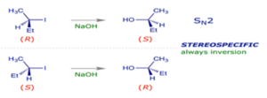
The best example of a stereospecific reaction is the SN2 substitution reaction. In this type of reaction, always an inversion of the configuration takes place at the product side.

The R reactants give the products of S configuration and the S reactant gives the product of R configuration.

Examples,

Stereoselective reactions are concerned with the reaction pathway and not with the stereochemistry of reactant, on the other hand, stereospecific reactions are only concerned with the stereochemistry of reactant and not with the favorable reaction pathway. Hence, stereospecific reactions become a subset of stereoselective reactions. Therefore all stereospecific reactions are stereoselective, but all stereoselective reactions are not stereospecific reactions.

Read more on Why Chemical Changes are Irreversible: Detailed Analysis

Frequently Asked Questions:

Question: What do you mean by the stereoselective reaction?

Answer: The stereoselective reaction means

The reactions in which more favorable reaction pathway is responsible for the formation of the stereoisomers of the product and gives more than one product, one of the product is major while other is minor which are stereoisomers of each other are called stereoselective reactions.

Question: What do you mean by the stereospecific reaction?

Answer: The stereospecific reaction means

The reactions in which stereochemistry of the starting material or reactant controls the stereochemistry of the product, gives only one specific product, are called stereospecific reactions.

Question: How can you tell if a reaction is stereoselective or stereospecific?

Answer: one can tell the reaction is stereoselective or stereospecific.

If the reaction shows the possibility of the formation of more than one or multiple products, but only one is produced in excess as a major product, then it is a stereoselective reaction.

If the stereoisomer of a different product is given by a different stereoisomer of the reactant, then it is a stereospecific reaction. If a starting material gives identical products in equal ratio then it is not a stereospecific reaction.

Question: Can a stereoselective and stereospecific reaction be both?

Answer: The reaction can be both stereoselective and stereospecific.

In stereoselective reaction, the more favorable reaction pathway is responsible for the formation of the stereoisomers of the product. In the case of stereospecific reaction stereochemistry of starting materials regulate the stereochemistry of the products. These terms describe different aspects of the reaction, it can be both stereoselective and stereospecific. Example,

Fig 6.1 N
Figure 5: Catalytic Hydrogenation

Question: Why all stereospecific reactions are stereoselective?

Answer: All stereospecific reactions are stereoselective.

As we know stereoselective reaction concerns only with the reaction pathway, on the other hand, stereospecific reactions are only concerned with the stereochemistry of the reactant and not with the favorable reaction pathway. Hence, stereospecific reactions become a subset of stereoselective reactions. Therefore all stereospecific reactions are stereoselective.

Question: Which reactions are stereoselective?

Answer: Following are the stereoselective reactions,

  1. Enantioselective hydride reduction of carbonyl compounds.
  2. Nucleophilic addition to a homochiral cyclic ketone.
  3. Nucleophilic addition to a racemic cyclic ketone.


Also Read:

What is a Heading Indicator Directional Gyro: A Comprehensive Guide for Science Students

what is a heading indicator directional gyro

A heading indicator, also known as a directional gyro (DG) or gyrocompass, is a critical flight instrument used in aircraft to provide the pilot with real-time information about the aircraft’s heading, or the direction in which the aircraft’s nose is pointed. This information is crucial for accurate navigation and control of the aircraft’s directional movement.

Understanding the Principles of a Heading Indicator Directional Gyro

The heading indicator works by using a gyroscope, which is a spinning wheel or rotor that remains stable in its position due to the principle of conservation of angular momentum. The gyroscope in a heading indicator spins at a rate of nearly 24,000 revolutions per minute (rpm) and maintains its orientation regardless of the aircraft’s movements.

Before takeoff, the pilot aligns the gyro’s axis with a known heading provided by the magnetic compass. During flight, the heading indicator measures how much the aircraft has turned around the stable axis of the gyro, which alters the heading reading on the gauge.

The Earth’s magnetic field serves as the main reference for heading indicators, with the instrument using this magnetic field to determine the aircraft’s heading in relation to the Earth’s North and South poles. This is based on the principle of geomagnetism, where the Earth’s magnetic field can be used as a reference for navigation.

Factors Affecting Heading Indicator Accuracy

what is a heading indicator directional gyro

However, heading indicators can experience drift as a result of the gyroscope, causing small inaccuracies. This drift is caused by various factors, including:

  1. Precession: The gyroscope can experience precession, which is the tendency of the spinning rotor to change the orientation of its axis of rotation in response to an applied force. This can be caused by factors such as aircraft acceleration, vibration, or temperature changes.

  2. Gyroscopic Drift: The gyroscope can also experience drift due to the inherent imperfections in the manufacturing process, leading to small changes in the rotor’s speed or axis orientation over time.

  3. Magnetic Variation: The Earth’s magnetic field can vary depending on the aircraft’s location, causing the heading indicator to display a different heading than the actual magnetic north.

To maintain the accuracy of the heading indicator, the pilot must regularly align it with the magnetic compass, which serves as the primary reference for the aircraft’s heading.

Factors Affecting Heading Indicator Stability

Turbulence or abrupt maneuvers can also cause temporary errors in heading indicators, as the gyroscope can be influenced by the aircraft’s attitude or bank angle. This can lead to temporary errors in the displayed heading during turns or maneuvers.

To mitigate these effects, newer aircraft are designed with damping mechanisms, such as viscous dampers or electronic stabilization systems, to help minimize the impact of turbulence and abrupt maneuvers on the heading indicator’s accuracy.

Heading Indicator Technical Specifications

In terms of technical specifications, a typical heading indicator has the following characteristics:

  • Gyroscope Spin Rate: 24,000 rpm
  • Heading Accuracy: ±5°
  • Compass Card Resolution: 5-degree increments

The instrument is designed to resist changes to its position and is connected to a compass card that moves with changes to the aircraft heading, displaying the compass rose direction.

Maintaining Heading Indicator Accuracy

To maintain the accuracy of the heading indicator, the instrument requires regular and delicate maintenance, including:

  1. Bearing Inspection: Checking for bearing failure or wear, which can cause the gyroscope to become unstable.
  2. Filter Cleaning: Keeping the system and gyro filters clean to ensure proper airflow and prevent contamination.
  3. Lubrication Avoidance: Avoiding the lubrication of fittings on vacuum gyros, as this can lead to bearing failure.
  4. Gyro Exercising: Powering up and operating the gyro for 30 minutes every six months to exercise the bearings and maintain their condition.

By following these maintenance procedures, pilots and aircraft technicians can ensure that the heading indicator remains accurate and reliable throughout the flight.

Heading Indicator in Modern Aircraft Navigation

While the heading indicator is an important navigation tool, modern aircraft utilize a combination of navigation instruments, including GPS, inertial navigation systems, and magnetic compasses, to ensure redundancy and enhance navigational accuracy.

These advanced navigation systems can provide more accurate and reliable heading information, as well as additional data points such as position, altitude, and speed, which can be used to cross-reference and validate the heading indicator’s readings.

Conclusion

In summary, the heading indicator directional gyro is a critical flight instrument that provides real-time information about an aircraft’s heading, allowing for accurate navigation and control of the aircraft’s directional movement. By understanding the principles, factors affecting accuracy, and maintenance requirements of this instrument, science students can gain a deeper appreciation for the complex systems that enable modern aviation.

Reference:
Heading Indicator: What It Is, How It Works, and What to Do If It Fails
How Directional Gyros Work
The Heading Indicator Explained: Why Pilots Must Master This Directional Flight Instrument

The Definitive Guide: How Much Does a Gallon of Milk Weigh?

how much does a gallon of milk weigh

A gallon of milk weighs approximately 8.6 pounds or 3.9 kilograms in the United States customary system. This weight is based on the density of milk, which is around 8.6 pounds per gallon. In the imperial system, one imperial gallon of milk would weigh around 10.32 lb. The weight of a gallon of milk can vary slightly depending on factors such as temperature and composition, but 8.6 pounds is a commonly used value for a standard gallon of milk.

Understanding the Weight of a Gallon of Milk

To fully comprehend the weight of a gallon of milk, we need to delve into the underlying principles and factors that contribute to this measurement.

Milk Density and Weight

The weight of a gallon of milk is directly related to the density of milk. Milk is a complex fluid composed of various components, including water, fat, proteins, carbohydrates, and minerals. The density of milk is primarily determined by the relative proportions of these components.

The average density of milk is approximately 1.032 g/mL or 8.6 lb/gal at 20°C (68°F). This means that a standard gallon of milk (3.785 liters) would weigh around 8.6 pounds or 3.9 kilograms.

The formula to calculate the weight of a gallon of milk is:

Weight of a gallon of milk = Density of milk × Volume of a gallon
Where:
– Density of milk = 8.6 lb/gal or 1.032 g/mL
– Volume of a gallon = 3.785 liters or 0.1337 cubic feet

Substituting the values, we get:
– Weight of a gallon of milk = 8.6 lb/gal × 3.785 L/gal = 32.51 lb
– Weight of a gallon of milk = 1.032 g/mL × 3785 mL/gal = 3,901.32 g

Therefore, a standard gallon of milk weighs approximately 8.6 pounds or 3.9 kilograms.

Factors Affecting Milk Weight

While the average weight of a gallon of milk is 8.6 pounds, there are several factors that can influence the exact weight:

  1. Milk Composition: The composition of milk, particularly the fat and protein content, can affect its density and, consequently, its weight. Milk with a higher fat content will have a slightly higher density and weight.

  2. Temperature: The temperature of the milk can also impact its density and weight. As the temperature increases, the volume of the milk expands, leading to a slight decrease in density and weight.

  3. Milk Processing: The processing methods used to produce milk, such as homogenization and pasteurization, can also affect the milk’s composition and, therefore, its weight.

  4. Milk Type: Different types of milk, such as whole milk, 2% milk, 1% milk, and skim milk, may have slightly different weights due to their varying fat and solid contents.

  5. Measurement Accuracy: The accuracy of the measurement tools and techniques used to determine the weight of a gallon of milk can also contribute to slight variations in the reported values.

Conversion between Units

To further understand the weight of a gallon of milk, it’s helpful to explore the conversions between different units of measurement.

  1. Gallon to Pound Conversion:
  2. 1 gallon of milk = 8.6 pounds

  3. Gallon to Kilogram Conversion:

  4. 1 gallon of milk = 3.9 kilograms

  5. Quart to Pound Conversion:

  6. 1 quart of milk = 2.15 pounds

  7. Ounce to Pound Conversion:

  8. 1 fluid ounce of milk = 0.0675 pounds
  9. 128 fluid ounces (1 gallon) = 8.6 pounds

  10. Liter to Kilogram Conversion:

  11. 1 liter of milk = 1.032 kilograms
  12. 3.785 liters (1 gallon) = 3.9 kilograms

These conversions can be useful in various applications, such as recipe calculations, meal planning, and transportation logistics.

Practical Applications and Considerations

how much does a gallon of milk weigh

The weight of a gallon of milk has several practical applications and considerations that are important to understand.

Milk Packaging and Transportation

The weight of a gallon of milk is a crucial factor in the packaging and transportation of milk products. Milk is typically sold in various container sizes, such as gallons, half-gallons, and quarts. The weight of these containers must be considered when designing packaging, determining shipping capacities, and optimizing transportation logistics.

For example, a standard milk crate can hold four one-gallon containers, which would weigh approximately 34.4 pounds (4 × 8.6 pounds). This information is essential for logistics planning, ensuring the safe and efficient transportation of milk products.

Meal Planning and Nutrition

The weight of a gallon of milk is also relevant in meal planning and nutrition calculations. When preparing recipes or calculating the nutritional content of a meal, the weight of the milk used can impact the overall calorie, protein, and nutrient values.

For instance, if a recipe calls for 1 cup of milk, and you need to determine the nutritional information, you can use the conversion of 1 gallon = 16 cups to calculate the weight of the milk used.

Milk Density and Composition

The density and weight of milk can also provide insights into the milk’s composition and quality. Variations in milk density and weight may indicate differences in fat, protein, or other solid content, which can be relevant for dairy producers, processors, and consumers.

Understanding the relationship between milk density, weight, and composition can be valuable in quality control, product development, and research applications within the dairy industry.

Conclusion

In summary, a gallon of milk weighs approximately 8.6 pounds or 3.9 kilograms in the United States customary system. This weight is primarily determined by the density of milk, which is around 8.6 pounds per gallon. However, factors such as milk composition, temperature, and processing can slightly influence the exact weight of a gallon of milk.

By understanding the weight of a gallon of milk and the underlying principles, you can apply this knowledge in various practical scenarios, including milk packaging, transportation, meal planning, and dairy industry applications. This comprehensive guide provides the necessary technical details and specific data points to help you navigate the intricacies of milk weight and density.

References:

  1. How much does milk weigh? – DAIReXNET. (2019-08-16). Retrieved from https://dairy-cattle.extension.org/how-much-does-milk-weigh/
  2. How much does a gallon of milk weigh? – Homework.Study.com. Retrieved from https://homework.study.com/explanation/how-much-does-a-gallon-of-milk-weigh.html
  3. How much does a gallon of Milk Weigh? | FYI – Vocal Media. Retrieved from https://vocal.media/fyi/how-much-does-a-gallon-of-milk-weigh
  4. How Much Does A Gallon of Milk Weigh? – Facts.net. Retrieved from https://facts.net/how-much-does-a-gallon-of-milk-weigh/

The Attitude Indicator: A Comprehensive Guide to the Artificial Horizon

what is attitude indicator artificial horizon

The attitude indicator, also known as the artificial horizon or gyro horizon, is a critical flight instrument that provides pilots with real-time information about an aircraft’s orientation relative to the Earth’s horizon. This instrument plays a crucial role in maintaining situational awareness and safe flight operations, particularly during periods of low visibility or when flying in instrument meteorological conditions (IMC). In this comprehensive guide, we will delve into the technical specifications, working principles, and the importance of the attitude indicator in modern aviation.

Understanding the Attitude Indicator

The attitude indicator is a flight instrument that measures and displays the aircraft’s pitch and bank/roll angles. It uses a gyroscope as its primary component, which is typically powered by the aircraft’s vacuum system or electrical system. The gyroscope’s vertical spin axis and the freely spinning gimbal rings on the lateral and longitudinal axes allow the instrument to accurately detect and display the aircraft’s pitch and roll attitudes.

Gyroscopic Principles

The attitude indicator’s operation is based on the principles of gyroscopic inertia. A gyroscope is a spinning wheel or rotor that maintains its orientation in space, regardless of the aircraft’s movements. This property, known as gyroscopic rigidity, is the foundation of the attitude indicator’s ability to provide a stable reference for the aircraft’s orientation.

The gyroscope in the attitude indicator is designed with a vertical spin axis, which allows it to sense and display the aircraft’s pitch and roll angles. The gimbal rings, which are free to rotate on the lateral and longitudinal axes, transfer the gyroscope’s orientation to the instrument’s display, providing the pilot with a visual representation of the aircraft’s attitude.

Pitch and Roll Indication

The attitude indicator’s display typically consists of a horizon line, which represents the Earth’s horizon, and a set of pitch and roll scales. The pitch scale, represented by horizontal lines, indicates the angle between the aircraft’s longitudinal axis and the horizon. These lines are typically spaced in 5-degree increments, both above and below the horizon line, allowing the pilot to accurately determine the aircraft’s pitch attitude.

The roll scale, on the other hand, is represented by a set of vertical lines or a bank angle indicator. This scale indicates the aircraft’s bank or roll angle, providing the pilot with information about the aircraft’s lateral orientation relative to the horizon.

Power Sources and Data Transmission

The attitude indicator can be powered by either the aircraft’s vacuum system or the electrical system, depending on the aircraft’s design and configuration. In older aircraft, the attitude indicator was typically driven by a vacuum-powered gyroscope, which was supplied by an onboard vacuum pump.

In modern glass cockpit aircraft, the attitude indicator is a solid-state instrument that receives its data from the Attitude Heading Reference System (AHRS), Inertial Reference Unit (IRU), and the Inertial Navigation System (INS). These systems use a combination of sensors, including accelerometers and magnetometers, to provide the attitude indicator with accurate and real-time information about the aircraft’s orientation.

Attitude Indicator Accuracy and Limitations

what is attitude indicator artificial horizon

The attitude indicator is generally considered a highly accurate and reliable instrument, but it is not without its limitations. The instrument’s performance can be affected by various factors, including the speed of the erection mechanism, the quality of the gyroscope, and the aircraft’s maneuvers.

Erection Mechanism and Errors

The erection mechanism is responsible for keeping the gyroscope’s spin axis aligned with the Earth’s gravity vector. This mechanism uses pendulous vanes or other devices to detect any deviation from the vertical and apply a corrective force to the gyroscope.

The speed at which the erection mechanism functions can affect the attitude indicator’s accuracy. During rapid acceleration or deceleration, the erection mechanism may not be able to keep up with the changes, leading to a slight nose-up or nose-down indication on the instrument.

Gyroscope Quality and Drift

The quality and precision of the gyroscope used in the attitude indicator can also impact its accuracy. High-quality gyroscopes are less susceptible to drift, which is the gradual change in the gyroscope’s orientation over time due to factors such as bearing wear, temperature changes, and vibrations.

Older attitude indicators, which used mechanical gyroscopes, were more prone to drift and required periodic calibration to maintain their accuracy. Modern solid-state attitude indicators, which use electronic gyroscopes, are generally less affected by drift and can provide more stable and reliable attitude information.

Pitch and Roll Limitations

Older mechanical attitude indicators had limitations in the amount of pitch and roll they could display. Typically, these instruments were limited to around 60 degrees of pitch and 100 degrees of roll. This was due to the physical constraints of the gimbal system and the need to maintain the gyroscope’s stability.

In contrast, modern solid-state attitude indicators can often handle a much wider range of pitch and roll angles, making them more suitable for high-performance aircraft and aerobatic maneuvers.

DIY Attitude Indicator: Challenges and Considerations

Building a DIY attitude indicator is a complex and challenging project that requires a deep understanding of gyroscopic principles, vacuum system design, and aircraft instrumentation. It involves sourcing or manufacturing a suitable gyroscope, designing and constructing the gimbal system, creating the artificial horizon display, and integrating the entire system with the aircraft’s electrical or vacuum system.

Gyroscope Selection and Fabrication

The selection or fabrication of the gyroscope is a critical component of a DIY attitude indicator project. The gyroscope must be of high quality, with minimal drift and excellent stability, to ensure accurate and reliable attitude information. This may require the use of specialized materials, precision machining, and advanced manufacturing techniques.

Gimbal System Design

The gimbal system, which allows the gyroscope to freely rotate on the lateral and longitudinal axes, is another crucial aspect of the DIY attitude indicator. The design of the gimbal system must account for factors such as weight, balance, and freedom of movement to ensure the accurate transfer of the gyroscope’s orientation to the display.

Display Integration

The artificial horizon display must be designed and integrated with the gyroscope and gimbal system to provide the pilot with a clear and intuitive representation of the aircraft’s attitude. This may involve the use of specialized electronics, software, and display technologies to ensure the instrument’s functionality and readability.

Vacuum or Electrical System Integration

Depending on the aircraft’s configuration, the DIY attitude indicator may need to be integrated with the aircraft’s vacuum system or electrical system. This integration requires a deep understanding of the aircraft’s power systems, as well as the ability to design and implement the necessary interfaces and connections.

Regulatory Considerations

In many jurisdictions, the installation of a DIY attitude indicator in an aircraft may be subject to strict regulatory requirements and certification processes. Pilots and aircraft owners considering such a project must ensure that they comply with all relevant aviation regulations and obtain the necessary approvals before attempting to install the instrument.

Conclusion

The attitude indicator, or artificial horizon, is a critical flight instrument that provides pilots with real-time information about an aircraft’s orientation relative to the Earth’s horizon. This instrument, which operates on the principles of gyroscopic inertia, plays a crucial role in maintaining situational awareness and safe flight operations, particularly in low-visibility or instrument meteorological conditions.

While building a DIY attitude indicator is a complex and challenging project, it can be a rewarding endeavor for those with a deep understanding of gyroscopic principles, aircraft instrumentation, and the regulatory requirements governing the installation of such devices. By mastering the technical details and design considerations outlined in this comprehensive guide, aspiring aviation enthusiasts and students can gain valuable insights into the inner workings of this essential flight instrument.

References:

  1. Hogrefe, E. (2013). The Attitude Indicator: A Fundamental Flight Instrument. Zeitschrift für Arbeitswissenschaft, 67(2), 168-178. https://econtent.hogrefe.com/doi/10.1027/2192-0923/a000168
  2. Pilot Mall. (n.d.). Watch Your Attitude: A Complete Guide to Aircraft Attitude Indicators. https://www.pilotmall.com/blogs/news/watch-your-attitude-a-complete-guide-to-aircraft-attitude-indicators
  3. Wikipedia. (n.d.). Attitude indicator. https://en.wikipedia.org/wiki/Attitude_indicator
  4. CFI Notebook. (n.d.). Attitude Indicator. https://www.cfinotebook.net/notebook/avionics-and-instruments/attitude-indicator
  5. Entire Flight. (2021). The Attitude Indicator: An In-Depth Overview of the 6 Pack’s Artificial Horizon. https://www.entireflight.com/blogs/learntofly/the-attitude-indicator-an-in-depth-overview-of-the-6-packs-artificial-horizon

Trebuchet vs Catapult vs Ballista: A Comprehensive Comparison

trebuchet vs catapult vs ballista

Trebuchets, catapults, and ballistas are all siege weapons used in medieval times for capturing or destroying castles. While they share the same purpose, these three siege engines have distinct differences in terms of cost, speed, strength, accuracy, and other unique features. This comprehensive guide will delve into the technical details and quantifiable data to help you understand the nuances between these formidable weapons.

The Trebuchet: The Pinnacle of Siege Weapon Technology

The trebuchet is considered the most technologically advanced of the three siege engines. It utilizes a counterweight mechanism to launch projectiles, making it more powerful and accurate than both the catapult and ballista.

The working principle of a trebuchet is based on the conversion of potential energy into kinetic energy. The potential energy is stored in the counterweight, which is then released, converting the stored energy into the kinetic energy that propels the projectile towards the target.

The key components of a trebuchet include:

  1. Counterweight: The counterweight is the primary source of the trebuchet’s power. It is typically made of heavy materials, such as stone or metal, and its weight can range from several hundred to several thousand kilograms.

  2. Throwing Arm: The throwing arm is the long, pivoting beam that is connected to the counterweight. When the counterweight is released, the throwing arm swings rapidly, launching the projectile.

  3. Sling: The sling is the attachment at the end of the throwing arm that holds the projectile. The sling is designed to release the projectile at the optimal angle and velocity.

Mathematically, the range of a trebuchet can be calculated using the following formula:

Range = (2 × v^2 × sin(2θ)) / g

Where:
v is the velocity of the projectile at launch
θ is the launch angle
g is the acceleration due to gravity

Some key data points for trebuchets:

  • Range: Trebuchets can launch projectiles up to 300 meters, making them the longest-range siege weapon of the three.
  • Accuracy: Trebuchets can achieve an accuracy of up to 90%, making them the most accurate of the three siege engines.
  • Cost: Trebuchets are the most expensive to build and maintain due to their complex counterweight mechanism, requiring more materials and skilled labor.
  • Speed: Trebuchets are the slowest to deploy and fire, as their counterweight mechanism requires more time to load and fire.

The Catapult: The Versatile Siege Engine

trebuchet vs catapult vs ballista

The catapult, while less powerful than the trebuchet, is more versatile and can be used in various ways, such as launching projectiles over walls or directly at them.

The catapult’s working principle is based on a torsion mechanism, which uses twisted ropes or springs to store and release energy, propelling the projectile.

The key components of a catapult include:

  1. Torsion Mechanism: The torsion mechanism is the heart of the catapult, responsible for storing and releasing the energy that launches the projectile. This mechanism typically consists of twisted ropes or springs.

  2. Throwing Arm: Similar to the trebuchet, the catapult has a throwing arm that is connected to the torsion mechanism. When the energy is released, the throwing arm swings rapidly, launching the projectile.

  3. Sling: The sling is the attachment at the end of the throwing arm that holds the projectile, just like in the trebuchet.

The range of a catapult can be calculated using the following formula:

Range = (v^2 × sin(2θ)) / g

Where:
v is the velocity of the projectile at launch
θ is the launch angle
g is the acceleration due to gravity

Some key data points for catapults:

  • Range: Catapults have a shorter range than trebuchets, typically around 100-150 meters.
  • Accuracy: Catapults have a lower accuracy rate than trebuchets, typically around 60-70%.
  • Cost: Catapults are less expensive to build and maintain than trebuchets, as their torsion mechanism is less complex.
  • Speed: Catapults are faster to deploy and fire than trebuchets, as their torsion mechanism requires less time to set up and fire.

The Ballista: The Crossbow of Siege Weapons

The ballista is a type of crossbow used for launching large arrows or bolts. While it is less powerful than both the trebuchet and catapult, it is more accurate and has a faster rate of fire.

The ballista’s working principle is based on a system of pulleys and levers that launch the projectile. This mechanism allows the ballista to be deployed and fired quickly, making it a versatile weapon for taking down walls or enemy soldiers.

The key components of a ballista include:

  1. Bow: The bow is the main source of the ballista’s power, storing the energy that is released to launch the projectile.
  2. Torsion Mechanism: The torsion mechanism, similar to the catapult, uses twisted ropes or springs to store and release the energy that powers the bow.
  3. Launching Mechanism: The launching mechanism consists of a system of pulleys and levers that transfer the energy from the torsion mechanism to the bow, propelling the projectile.

The range of a ballista can be calculated using the following formula:

Range = (v^2 × sin(2θ)) / g

Where:
v is the velocity of the projectile at launch
θ is the launch angle
g is the acceleration due to gravity

Some key data points for ballistas:

  • Range: Ballistas have the shortest range of the three siege engines, typically around 50-100 meters.
  • Accuracy: Ballistas have the lowest accuracy rate of the three, typically around 50-60%.
  • Cost: Ballistas are the least expensive to build and maintain, as their mechanism is relatively simple compared to the trebuchet and catapult.
  • Speed: Ballistas are the fastest to deploy and fire, thanks to their simple crossbow mechanism.

Comparison and Conclusion

To summarize the key differences between the three siege engines:

Feature Trebuchet Catapult Ballista
Range Longest (up to 300 m) Shorter (100-150 m) Shortest (50-100 m)
Accuracy Highest (up to 90%) Lower (60-70%) Lowest (50-60%)
Cost Most expensive Less expensive than trebuchet Least expensive
Speed Slowest to deploy and fire Faster than trebuchet Fastest to deploy and fire

While all three siege engines serve the same purpose, the trebuchet, catapult, and ballista each have their own unique strengths and weaknesses. The choice of which to use would depend on the specific tactical requirements of the siege, the available resources, and the desired outcome.

References:
Reddit Discussion on Trebuchet vs Catapult vs Ballista
Catapults Education Guide
Ballista, Catapult or Trebuchet Discussion