Exploring the Intricacies of Magnetic Field and Time

magnetic field and time

The strength of a magnetic field is a crucial parameter in various scientific and technological applications, ranging from geophysical exploration to medical imaging. The measurement and analysis of magnetic fields are often intertwined with the concept of time, as the temporal variations of these fields can provide valuable insights into the underlying physical processes. In this comprehensive blog post, we will delve into the intricate relationship between magnetic field and time, exploring the technical details, practical applications, and the latest advancements in this fascinating field of study.

Understanding Magnetic Field Strength

Magnetic field strength is typically measured in units of tesla (T) in the SI system or gauss (G) in the CGS system, where 1 T is equivalent to 10,000 G. The Earth’s magnetic field, for instance, can vary from 20,000 to 80,000 nanotesla (nT), depending on the location. This variation is due to the complex interplay of various factors, including the Earth’s core dynamics, solar activity, and local geological features.

To measure magnetic fields, scientists and engineers employ a range of specialized instruments called magnetometers. These devices come in different types, such as gaussmeters and teslameters, each designed to measure magnetic fields in their respective units. The choice of magnetometer depends on the specific application and the required level of precision.

Magnetic Field Measurement Techniques

  1. Aeromagnetic Surveys: These surveys are conducted from aircraft, providing a comprehensive mapping of the Earth’s magnetic field over large areas. Aeromagnetic data is used to search for mineral deposits, map geological structures, and even locate lost objects.

  2. Borehole Surveys: Magnetometers are lowered into boreholes to measure the magnetic field within the subsurface, which can reveal information about the geological composition and structure of the Earth’s crust.

  3. Ground Surveys: Ground-based magnetic surveys involve the use of portable magnetometers to measure the magnetic field at specific locations on the Earth’s surface. These surveys are often used in archaeological investigations and mineral exploration.

  4. Marine Surveys: Magnetometers mounted on ships or towed behind them are used to map the magnetic field of the seafloor, which can provide insights into the Earth’s geological history and the presence of mineral resources.

  5. Magnetovision Imaging: This technique involves the generation of images based on the spatial distribution of magnetic field parameters, allowing for detailed analysis and data fusion with other geophysical data.

  6. Magnetic Gradiometers: These instruments consist of pairs of magnetometers with their sensors separated by a fixed distance. They measure the difference between the sensed magnetic fields, enabling the detection of magnetic anomalies and their gradients, which can be useful in archaeological and site investigation work.

Temporal Aspects of Magnetic Fields

magnetic field and time

The performance and capabilities of magnetometers are often described through technical specifications, including the sample rate (number of readings per second) and cycle time (seconds per reading). These parameters are particularly important in mobile surveys, where accurate measurements are crucial for mapping the spatial and temporal variations of magnetic fields.

Magnetic Field Variations over Time

  1. Diurnal Variations: The Earth’s magnetic field exhibits daily (diurnal) variations due to the interaction between the Earth’s magnetic field and the ionosphere, which is influenced by solar activity.

  2. Secular Variations: The Earth’s magnetic field also undergoes gradual changes over longer timescales, known as secular variations. These changes are caused by the complex dynamics within the Earth’s core and can be used to study the planet’s geological history.

  3. Magnetic Storms: Sudden and intense disturbances in the Earth’s magnetic field, known as magnetic storms, are often triggered by solar activity, such as coronal mass ejections. These events can have significant impacts on various technological systems, including communication networks and power grids.

  4. Magnetic Pulsations: Rapid fluctuations in the Earth’s magnetic field, known as magnetic pulsations, can occur due to various factors, such as solar wind interactions and magnetospheric processes. These pulsations can provide insights into the dynamics of the Earth’s magnetosphere.

Temporal Sampling and Resolution

The temporal sampling and resolution of magnetic field measurements are crucial for capturing the dynamic nature of these fields. High sample rates and short cycle times are essential for accurately mapping the spatial and temporal variations of magnetic fields, particularly in mobile surveys or when studying rapid magnetic field changes.

For example, in aeromagnetic surveys, the sample rate can range from 10 to 20 readings per second, ensuring that the aircraft’s motion is adequately captured. In contrast, ground-based surveys may have lower sample rates, but the cycle time is still an important factor in ensuring the temporal resolution of the measurements.

Practical Applications and Advancements

The measurement and analysis of magnetic fields over time have numerous practical applications, ranging from geophysical exploration to medical imaging and beyond.

Geophysical Exploration

Magnetic surveys, both in the air and on the ground, are widely used in the search for mineral deposits, such as iron ore, copper, and gold. The temporal variations of magnetic fields can also provide insights into the Earth’s geological history and the presence of hidden structures or anomalies.

Archaeology and Site Investigation

Magnetic gradiometers, which measure the spatial gradients of magnetic fields, have become invaluable tools in archaeological investigations. These instruments can detect subtle magnetic anomalies, which may indicate the presence of buried structures, artifacts, or other features of archaeological significance.

Medical Imaging

Magnetometers play a crucial role in medical imaging techniques, such as magnetoencephalography (MEG) and magnetocardiography (MCG). These methods use the magnetic fields generated by the brain and heart, respectively, to provide non-invasive insights into their function and structure.

Space Weather Monitoring

The monitoring of the Earth’s magnetic field, including its temporal variations, is essential for understanding and predicting space weather events, such as solar storms and their potential impacts on technological systems.

Advancements in Magnetometer Technology

Ongoing research and development in magnetometer technology have led to the creation of more sensitive, accurate, and compact devices. For example, the emergence of quantum magnetometers has significantly improved the precision and stability of magnetic field measurements, opening up new possibilities in various applications.

Conclusion

The interplay between magnetic field and time is a fascinating and multifaceted topic that encompasses a wide range of scientific and technological disciplines. From geophysical exploration to medical imaging, the measurement and analysis of magnetic fields over time have become essential tools for understanding the complex dynamics of our planet and the universe beyond. As research and technological advancements continue to push the boundaries of what is possible, the future of magnetic field and time studies holds the promise of even greater insights and applications.

References:

  1. Blakely, R. J. (1995). Potential Theory in Gravity and Magnetic Applications. Cambridge University Press.
  2. Hinze, W. J., Von Frese, R. R., & Saad, A. H. (2013). Gravity and Magnetic Exploration: Principles, Practices, and Applications. Cambridge University Press.
  3. Merrill, R. T., McElhinny, M. W., & McFadden, P. L. (1996). The Magnetic Field of the Earth: Paleomagnetism, the Core, and the Deep Mantle. Academic Press.
  4. Paperno, E., Lehtinen, J., & Iivanainen, J. (2015). Magnetocardiography. Wiley Encyclopedia of Electrical and Electronics Engineering.
  5. Vrba, J., & Robinson, S. E. (2001). Signal Processing in Magnetoencephalography. Methods, 25(2), 249-271.
Magnetic Flux and Magnetic Induction 2: A Comprehensive Guide

magnetic flux and magnetic induction 2

Magnetic flux and magnetic induction are fundamental concepts in electromagnetism, describing the behavior of magnetic fields and the electromotive force induced in coils due to changing magnetic flux. This comprehensive guide delves into the technical details, formulas, and applications of these principles, providing a valuable resource for physics students and enthusiasts.

Understanding Magnetic Flux

Magnetic flux, denoted by the Greek letter Phi or the Phi suffix B (ϕ or ϕB), is the measure of the total magnetic field that penetrates a specified closed surface. It is quantified by counting the magnetic field lines that intersect the surface. The SI unit of magnetic flux is the Weber (Wb).

The formula for calculating the magnetic flux through a coil cross-sectional area is:

ϕB = BA cos θ

Where:
– ϕB is the magnetic flux (in Webers)
– B is the magnetic field strength (in Teslas)
– A is the cross-sectional area of the coil (in square meters)
– θ is the angle between the magnetic field lines and the normal to the coil’s surface (in radians)

This formula demonstrates the relationship between the magnetic field, the area of the coil, and the angle at which the magnetic field lines pass through the coil.

Magnetic Flux Density

Magnetic flux density, also known as magnetic induction, is the physical quantity used as one of the fundamental measures of the intensity of a magnetic field. It is represented by the symbol B and its SI unit is the Tesla (T).

The magnetic flux density is defined as the magnetic flux per unit area, and it can be calculated using the formula:

B = ϕB / A

Where:
– B is the magnetic flux density (in Teslas)
– ϕB is the magnetic flux (in Webers)
– A is the cross-sectional area (in square meters)

Magnetic flux density is an important concept in various applications, such as the design of electrical machines, transformers, and magnetic resonance imaging (MRI) systems.

Faraday’s Law of Induction

magnetic flux and magnetic induction 2

Faraday’s law of induction describes the relationship between the changing magnetic flux and the induced electromotive force (EMF) in a coil. The formula for the induced EMF is:

V = -N (dϕB/dt)

Where:
– V is the induced EMF (in volts)
– N is the number of turns in the coil
– dϕB/dt is the rate of change of the magnetic flux with respect to time (in Webers per second)

The negative sign in the formula indicates that the induced EMF opposes the change in the magnetic flux, as described by Lenz’s law.

Applications of Faraday’s Law

Faraday’s law of induction has numerous applications in various fields, including:

  1. Electrical Generators: The principle of electromagnetic induction, as described by Faraday’s law, is the basis for the operation of electrical generators, where the relative motion between a conductor and a magnetic field induces an EMF.

  2. Transformers: Transformers rely on the principle of electromagnetic induction to transfer electrical energy between two or more circuits through a shared magnetic field.

  3. Eddy Current Brakes: Eddy current brakes use the induced EMF in a conductive material to create a braking force, which is useful in applications such as elevators, cranes, and roller coasters.

  4. Magnetic Induction Accelerometers: The acceleration due to gravity (g) can be measured using magnetic induction, where a falling bar magnet induces a voltage in a series of coils, and the crossing times are used to calculate the value of g.

Measuring Acceleration Due to Gravity (g) Using Magnetic Induction

One practical application of magnetic flux and induction is the measurement of the acceleration due to gravity (g) using a magnetic induction-based approach. This method involves the following steps:

  1. Signal Acquisition: The signal is acquired using an Arduino Uno board, which is a popular open-source microcontroller platform.

  2. Data Analysis: The acquired signal is analyzed using a Python-based graphical user interface (GUI), which allows for the processing and visualization of the data.

  3. Calculation of g: The acceleration due to gravity (g) is calculated by measuring the crossing times of a bar magnet as it falls simultaneously through a number of coils. This method is based on Faraday’s law of induction and the relationship between the magnetic flux and the magnetic field.

The key steps in this process are:

  1. Dropping a bar magnet through a series of coils
  2. Measuring the time it takes for the magnet to pass through each coil
  3. Calculating the acceleration due to gravity (g) using the crossing times and the known distance between the coils

By applying the principles of magnetic flux and induction, this method provides a practical and accessible way to measure the acceleration due to gravity, making it a valuable tool for physics education and research.

Numerical Examples and Problems

To further illustrate the concepts of magnetic flux and induction, let’s consider some numerical examples and problems:

Example 1: Calculating Magnetic Flux

A circular coil with a radius of 5 cm is placed in a uniform magnetic field of 0.8 T, with the magnetic field lines perpendicular to the plane of the coil. Calculate the magnetic flux through the coil.

Given:
– Radius of the coil, r = 5 cm = 0.05 m
– Magnetic field strength, B = 0.8 T
– Angle between the magnetic field and the normal to the coil’s surface, θ = 0° (perpendicular)

Using the formula: ϕB = BA cos θ
ϕB = (0.8 T) × (π × (0.05 m)^2) × cos(0°)
ϕB = 0.0628 Wb

Therefore, the magnetic flux through the circular coil is 0.0628 Wb.

Problem 1: Induced EMF in a Coil

A coil with 100 turns is placed in a uniform magnetic field of 0.5 T. The coil has a cross-sectional area of 0.02 m^2 and is rotated from a position where the magnetic field is perpendicular to the coil’s surface to a position where the magnetic field is parallel to the coil’s surface in 0.1 seconds.

Calculate the induced EMF in the coil.

Given:
– Number of turns in the coil, N = 100
– Magnetic field strength, B = 0.5 T
– Cross-sectional area of the coil, A = 0.02 m^2
– Time taken to rotate the coil, t = 0.1 s
– Initial angle, θ = 90° (perpendicular)
– Final angle, θ = 0° (parallel)

Using the formula: V = -N (dϕB/dt)
dϕB/dt = (ϕB,final – ϕB,initial) / t
dϕB/dt = [(BA cos 0°) – (BA cos 90°)] / 0.1 s
dϕB/dt = (0.5 T × 0.02 m^2 × 1 – 0.5 T × 0.02 m^2 × 0) / 0.1 s
dϕB/dt = 0.1 Wb/s

Substituting in the formula for induced EMF:
V = -N (dϕB/dt)
V = -100 × 0.1 Wb/s
V = -10 V

Therefore, the induced EMF in the coil is -10 V.

These examples and problems demonstrate the application of the formulas and principles related to magnetic flux and induction, providing a deeper understanding of these concepts.

Conclusion

Magnetic flux and magnetic induction are fundamental concepts in electromagnetism that are crucial for understanding the behavior of magnetic fields and the induced electromotive force in coils. This comprehensive guide has explored the technical details, formulas, and applications of these principles, including the measurement of the acceleration due to gravity using magnetic induction.

By delving into the specifics of magnetic flux, flux density, Faraday’s law of induction, and practical applications, this guide aims to serve as a valuable resource for physics students and enthusiasts, providing a solid foundation in these essential electromagnetic phenomena.

References

  1. Geeksforgeeks.org. (n.d.). Magnetic Flux. [online] Available at: https://www.geeksforgeeks.org/magnetic-flux/ [Accessed 1 May 2023].
  2. IOP Publishing. (2023). Measuring the acceleration due to gravity using magnetic induction. [online] Available at: https://iopscience.iop.org/article/10.1088/1361-6552/acb033 [Accessed 1 May 2023].
  3. e-magnetica.pl. (n.d.). Magnetic Flux Density. [online] Available at: https://www.e-magnetica.pl/doku.php/magnetic_flux_density [Accessed 1 May 2023].
  4. Phys.libretexts.org. (n.d.). 22.1: Magnetic Flux, Induction, and Faraday’s Law. [online] Available at: https://phys.libretexts.org/Bookshelves/University_Physics/Physics_%28Boundless%29/22%3A_Induction_AC_Circuits_and_Electrical_Technologies/22.1%3A_Magnetic_Flux_Induction_and_Faradays_Law [Accessed 1 May 2023].

Is Magnetic Field Constant: A Comprehensive Guide for Physics Students

is magnetic field constant

The magnetic field constant, also known as the permeability of free space, is a fundamental physical constant that plays a crucial role in various electromagnetic phenomena. This constant, denoted as μ₀, has a fixed value of 4π × 10⁻⁷ N/A², where N stands for Newton, A for Ampere, and T for Tesla. Understanding the significance and applications of this constant is essential for physics students to grasp the underlying principles of electromagnetism.

The Significance of the Magnetic Field Constant

The magnetic field constant, μ₀, is a fundamental quantity that appears in numerous physics formulas and relationships. It is a measure of the ability of free space to support a magnetic field and is a crucial parameter in the study of electromagnetic phenomena. Some of the key applications and significance of the magnetic field constant include:

  1. Magnetic Field of a Solenoid: The magnetic field produced by a solenoid can be expressed as B = μ₀NI/L, where N is the number of turns of wire in the coil, I is the current flowing through the coil, and L is the length of the coil. The magnetic field constant, μ₀, is a crucial factor in this equation, as it determines the strength of the magnetic field.

  2. Magnetic Field of a Current-Carrying Wire: The magnetic field produced by a current-carrying wire follows the relationship B = μ₀I/(2πr), where I is the current and r is the distance from the wire. The magnetic field constant, μ₀, is again a fundamental component of this equation.

  3. Electromagnetic Induction: The magnetic field constant, μ₀, appears in the equations describing electromagnetic induction, such as Faraday’s law of electromagnetic induction and Lenz’s law. These laws govern the generation of induced currents and voltages due to changing magnetic fields.

  4. Magnetic Flux Density: The magnetic flux density, or magnetic induction, is defined as B = μ₀H, where H is the magnetic field strength. The magnetic field constant, μ₀, is used to convert the magnetic field strength to the magnetic flux density, which is a crucial quantity in the study of magnetic materials and devices.

  5. Magnetic Energy Density: The energy density of a magnetic field is given by the equation U = (B²)/(2μ₀), where U is the energy density and B is the magnetic flux density. The magnetic field constant, μ₀, is a key factor in this equation, as it relates the magnetic flux density to the energy stored in the magnetic field.

Experimental Determination of the Magnetic Field Constant

is magnetic field constant

The magnetic field constant, μ₀, can be determined experimentally through various methods. One common approach is to measure the magnetic field produced by a current-carrying wire or a solenoid and then use the appropriate formula to calculate the value of μ₀. Here’s an example of how this can be done:

  1. Measuring the Magnetic Field of a Solenoid: Set up a solenoid with a known number of turns, N, and measure the current, I, flowing through the coil. Using a magnetic field sensor or a Hall effect probe, measure the magnetic field, B, at a specific distance inside the solenoid. Rearranging the formula B = μ₀NI/L, you can solve for the value of μ₀.

  2. Measuring the Magnetic Field of a Current-Carrying Wire: Measure the current, I, flowing through a long, straight wire and the distance, r, from the wire. Using a magnetic field sensor, measure the magnetic field, B, at the specified distance. Rearranging the formula B = μ₀I/(2πr), you can solve for the value of μ₀.

It’s important to note that when performing these experiments, you should consider the potential sources of error and uncertainty, such as the accuracy of the measurement instruments, the alignment of the solenoid or wire, and the environmental conditions. By taking these factors into account, you can obtain a reliable estimate of the magnetic field constant, μ₀.

Theoretical Derivation of the Magnetic Field Constant

The magnetic field constant, μ₀, can also be derived theoretically from fundamental principles of electromagnetism. One approach is to use the definition of the ampere, which is the base unit of electric current in the International System of Units (SI). The ampere is defined as the constant flow of one coulomb of electric charge per second.

Using this definition, along with the relationship between the magnetic field and the current-carrying wire, it is possible to derive the value of the magnetic field constant, μ₀. This theoretical derivation involves the use of Maxwell’s equations, which describe the fundamental laws of electromagnetism.

The theoretical value of the magnetic field constant, μ₀, is:

μ₀ = 4π × 10⁻⁷ N/A²

This value is in agreement with the experimentally determined value, and it is a fundamental constant that appears in various electromagnetic equations and relationships.

Applications of the Magnetic Field Constant

The magnetic field constant, μ₀, has numerous applications in various fields of physics and engineering. Some of the key applications include:

  1. Magnetic Resonance Imaging (MRI): MRI technology relies on the interaction between the magnetic field and the magnetic moments of atomic nuclei within the human body. The magnetic field constant, μ₀, is a crucial parameter in the equations that describe the behavior of these magnetic moments and the resulting MRI signals.

  2. Particle Accelerators: In particle accelerators, such as cyclotrons and synchrotrons, charged particles are guided and accelerated using strong magnetic fields. The magnetic field constant, μ₀, is a key factor in the design and operation of these particle accelerators.

  3. Electromagnetic Devices: The magnetic field constant, μ₀, is essential in the design and analysis of various electromagnetic devices, such as transformers, motors, generators, and electromagnets. It is used to calculate the magnetic flux, magnetic energy, and other important parameters in these devices.

  4. Electromagnetic Waves: The magnetic field constant, μ₀, appears in the equations that describe the propagation of electromagnetic waves, such as light, radio waves, and microwaves. It is a fundamental parameter in the study of wave-based communication systems and optical devices.

  5. Plasma Physics: In the study of plasma physics, the magnetic field constant, μ₀, is used to describe the behavior of charged particles in magnetic fields, which is crucial for understanding phenomena such as fusion reactors and astrophysical plasmas.

By understanding the significance and applications of the magnetic field constant, μ₀, physics students can develop a deeper appreciation for the fundamental principles of electromagnetism and their practical implications in various scientific and technological fields.

Numerical Examples and Problems

To further solidify your understanding of the magnetic field constant, let’s explore some numerical examples and problems:

  1. Magnetic Field of a Solenoid:
  2. Given: A solenoid has 500 turns of wire and carries a current of 2 A. The length of the solenoid is 20 cm.
  3. Calculate the magnetic field inside the solenoid using the formula B = μ₀NI/L.
  4. Solution: B = (4π × 10⁻⁷ N/A²) × (500 turns) × (2 A) / (0.2 m) = 6.28 × 10⁻³ T

  5. Magnetic Field of a Current-Carrying Wire:

  6. Given: A long, straight wire carries a current of 5 A. The distance from the wire is 10 cm.
  7. Calculate the magnetic field at the specified distance using the formula B = μ₀I/(2πr).
  8. Solution: B = (4π × 10⁻⁷ N/A²) × (5 A) / (2π × 0.1 m) = 1 × 10⁻⁵ T

  9. Magnetic Energy Density:

  10. Given: A magnetic field with a flux density of 1 T is present in a region of space.
  11. Calculate the energy density of the magnetic field using the formula U = (B²)/(2μ₀).
  12. Solution: U = (1 T)² / (2 × 4π × 10⁻⁷ N/A²) = 3.98 × 10⁻⁴ J/m³

  13. Magnetic Flux Density:

  14. Given: A magnetic field with a strength of 800 A/m is present in a region of space.
  15. Calculate the magnetic flux density using the formula B = μ₀H.
  16. Solution: B = (4π × 10⁻⁷ N/A²) × (800 A/m) = 1 × 10⁻³ T

These examples demonstrate how the magnetic field constant, μ₀, is used in various electromagnetic equations and calculations. By working through these problems, physics students can gain a deeper understanding of the practical applications of the magnetic field constant and its role in the study of electromagnetism.

Conclusion

The magnetic field constant, μ₀, is a fundamental physical constant that plays a crucial role in the study of electromagnetism. Its fixed value of 4π × 10⁻⁷ N/A² appears in numerous physics formulas and relationships, making it an essential parameter in the understanding and analysis of various electromagnetic phenomena.

By exploring the significance, experimental determination, theoretical derivation, and applications of the magnetic field constant, physics students can develop a comprehensive understanding of this important concept. The numerical examples and problems provided in this guide further reinforce the practical applications of the magnetic field constant and its relevance in various fields of physics and engineering.

As you continue your studies in electromagnetism, remember the importance of the magnetic field constant and its role in shaping our understanding of the physical world. Mastering this concept will not only deepen your knowledge but also equip you with the necessary tools to tackle more advanced topics in the field of physics.

References

  1. Griffiths, D. J. (2013). Introduction to Electromagnetism (4th ed.). Pearson.
  2. Serway, R. A., & Jewett, J. W. (2014). Physics for Scientists and Engineers with Modern Physics (9th ed.). Cengage Learning.
  3. Halliday, D., Resnick, R., & Walker, J. (2013). Fundamentals of Physics (10th ed.). Wiley.
  4. Tipler, P. A., & Mosca, G. (2008). Physics for Scientists and Engineers (6th ed.). W. H. Freeman.
  5. Nave, C. R. (n.d.). HyperPhysics. Georgia State University. http://hyperphysics.phy-astr.gsu.edu/hbase/hframe.html

Magnetic Field Between Two Parallel Wires: A Comprehensive Guide

magnetic field between two parallel wires

Summary

The magnetic field between two parallel wires is a fundamental concept in electromagnetism, with numerous applications in various fields of physics and engineering. This comprehensive guide will delve into the detailed analysis of the magnetic field and the associated forces between two parallel current-carrying wires, providing a thorough understanding of the underlying principles and practical applications.

Understanding the Magnetic Field Between Parallel Wires

magnetic field between two parallel wires

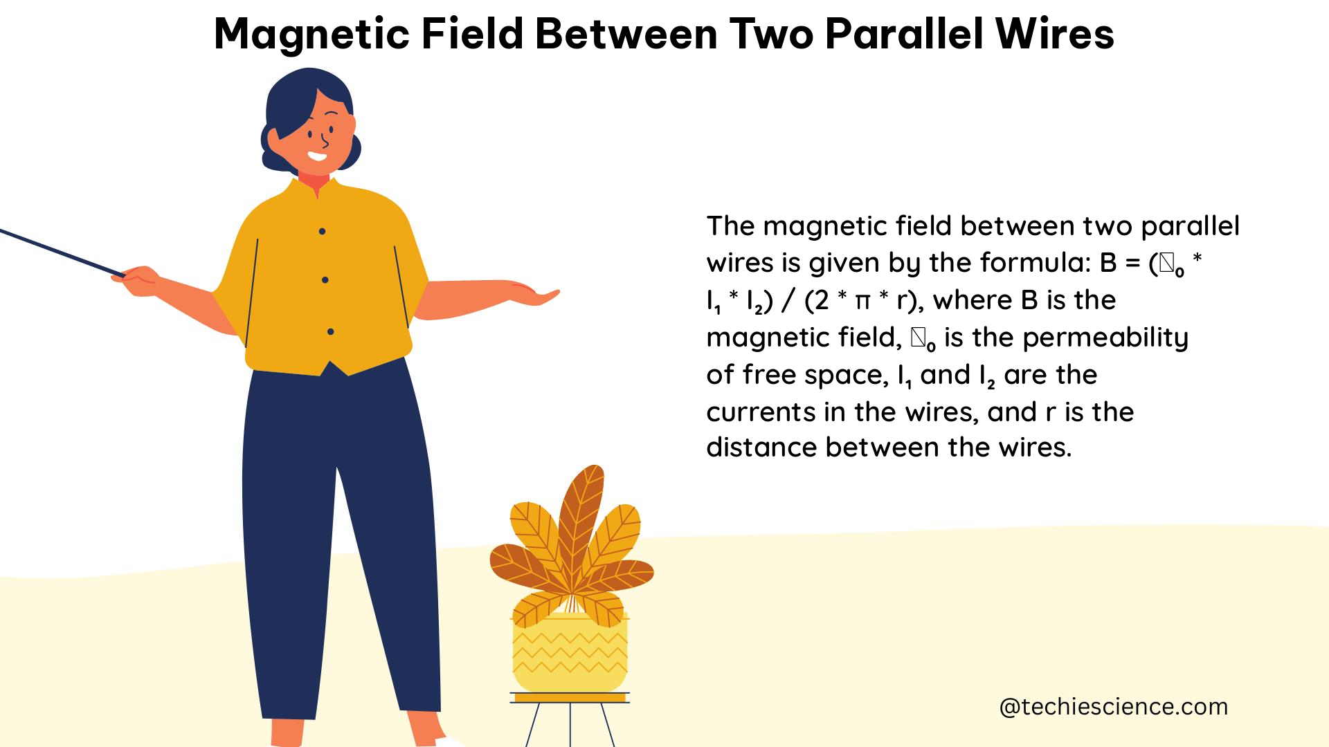
The magnetic field between two parallel wires can be calculated using the formula:

B = μ0 * I / (2 * π * d)

where:
B is the magnetic field strength (in Tesla, T)
μ0 is the permeability of free space (4π × 10^-7 T⋅m/A)
I is the current flowing through the wires (in Amperes, A)
d is the distance between the two parallel wires (in meters, m)

This formula is derived from the Biot-Savart law, which describes the magnetic field generated by a current-carrying wire.

Factors Affecting the Magnetic Field

The magnetic field between two parallel wires is influenced by several key factors:

  1. Current Magnitude: The strength of the magnetic field is directly proportional to the current flowing through the wires. Doubling the current will result in a doubling of the magnetic field.

  2. Distance Between Wires: The magnetic field decreases inversely with the distance between the wires. Doubling the distance between the wires will result in a halving of the magnetic field.

  3. Permeability of the Medium: The magnetic field is also affected by the permeability of the medium surrounding the wires. In this case, the formula assumes the wires are in a vacuum or air, where the permeability is that of free space (μ0).

Practical Example

Let’s consider a practical example to illustrate the calculation of the magnetic field between two parallel wires.

Suppose we have two parallel wires carrying a current of 10 Amperes (A) and the distance between them is 2 centimeters (cm) or 0.02 meters (m).

Using the formula:

B = μ0 * I / (2 * π * d)
B = (4π × 10^-7 T⋅m/A) × (10 A) / (2 × π × 0.02 m)
B = 0.01 Tesla (T)

Therefore, the magnetic field between the two parallel wires is 0.01 Tesla (T).

Magnetic Force Between Parallel Wires

In addition to the magnetic field, the interaction between the two parallel wires also results in a magnetic force. This force can be calculated using the formula:

F = μ0 * I1 * I2 / (2 * π * d)

where:
F is the magnetic force between the wires (in Newtons, N)
I1 and I2 are the currents flowing through the respective wires (in Amperes, A)
d is the distance between the two parallel wires (in meters, m)

Attractive and Repulsive Forces

The direction of the magnetic force between the parallel wires depends on the relative direction of the currents:

  1. Attractive Force: If the currents in the two wires are in the same direction, the magnetic force between them will be attractive.
  2. Repulsive Force: If the currents in the two wires are in opposite directions, the magnetic force between them will be repulsive.

Practical Example

Let’s consider the same example as before, where we have two parallel wires carrying a current of 10 Amperes (A) and the distance between them is 2 centimeters (cm) or 0.02 meters (m).

Using the formula:

F = μ0 * I1 * I2 / (2 * π * d)
F = (4π × 10^-7 T⋅m/A) × (10 A) × (10 A) / (2 × π × 0.02 m)
F = 0.002 Newtons (N)

Therefore, the magnetic force between the two parallel wires is 0.002 Newtons (N), and the direction of the force will depend on the relative direction of the currents in the wires.

Practical Applications and Considerations

The understanding of the magnetic field and force between parallel wires has numerous practical applications in various fields, including:

  1. Electrical Circuits: The magnetic field and force between parallel wires are crucial in the design and analysis of electrical circuits, particularly in the context of transformers, motors, and generators.

  2. Electromagnetic Devices: The principles of magnetic field and force between parallel wires are fundamental to the operation of various electromagnetic devices, such as solenoids, relays, and electromagnetic actuators.

  3. Particle Accelerators: In particle accelerators, such as cyclotrons and synchrotrons, the magnetic field between parallel wires is used to guide and control the motion of charged particles.

  4. Magnetic Levitation: The repulsive magnetic force between parallel wires can be utilized in magnetic levitation systems, where objects are suspended in the air without physical contact.

  5. Magnetic Shielding: The magnetic field between parallel wires can be used to create magnetic shielding, which is important in protecting sensitive electronic equipment from external magnetic interference.

When working with magnetic fields and forces between parallel wires, it is essential to consider factors such as the material properties of the wires, the presence of ferromagnetic materials, and the potential for electromagnetic interference with other nearby systems.

Conclusion

The magnetic field and force between two parallel wires are fundamental concepts in electromagnetism with a wide range of practical applications. By understanding the underlying principles, formulas, and the factors that influence these phenomena, physicists, engineers, and researchers can effectively design, analyze, and optimize various electromagnetic systems and devices. This comprehensive guide provides a detailed exploration of the topic, equipping readers with the necessary knowledge and tools to navigate the complexities of magnetic field interactions between parallel wires.

Reference:

  1. Magnetic Force between Two Parallel Conductors
  2. Attraction between two wires with parallel current
  3. Calculating Magnetic Field Between Parallel Wires
  4. Magnetic Force Between Two Parallel Current Carrying Wires
  5. Magnetic Force between Two Parallel Currents

Magnetic Field and Distance: A Comprehensive Guide for Physics Students

magnetic field and distance

Magnetic field and distance are closely related, with the strength of a magnetic field decreasing as the distance from its source increases. This relationship can be quantified through various experiments and calculations, providing a deeper understanding of magnetism and its properties.

Understanding the Inverse Square Law of Magnetic Fields

The relationship between magnetic field strength and distance is governed by the inverse square law, which states that the magnetic field strength is inversely proportional to the square of the distance from the source. This can be expressed mathematically as:

B = k / r^2

Where:
– B is the magnetic field strength
– k is a constant that depends on the source of the magnetic field
– r is the distance from the source of the magnetic field

This means that as the distance from the source of the magnetic field increases, the field strength decreases exponentially. For example, if you double the distance from the source, the magnetic field strength will decrease by a factor of four.

Measuring Magnetic Field Strength with a Gaussmeter

magnetic field and distance

One way to measure the magnetic field strength and its relationship with distance is by building a gaussmeter. This involves creating a circuit that can measure the strength of a magnetic field and observing how the field strength changes with distance.

The basic steps to build a gaussmeter are:

  1. Obtain a Hall effect sensor, which is a device that can measure the strength of a magnetic field.
  2. Create a circuit that can convert the voltage output of the Hall effect sensor into a reading of the magnetic field strength.
  3. Calibrate the gaussmeter by placing it in a known magnetic field and adjusting the circuit to display the correct field strength.
  4. Take voltage readings at different distances from a magnet and use the sensor’s sensitivity and Equation 1 to convert these readings to magnetic field strength.
  5. Plot the magnetic field strength against distance to visualize how the field strength changes with distance.

By following this process, you can create a custom gaussmeter and use it to explore the relationship between magnetic field strength and distance.

Measuring Relative Magnetic Field Strength with a Compass

Another way to measure the relationship between magnetic field strength and distance is by using a compass and a permanent magnet. This method involves:

  1. Placing the permanent magnet at selected distances from the compass.
  2. Measuring the deflection of the compass needle at each distance.
  3. Calculating the relative magnetic field strength using the formula:

Relative Magnetic Field Strength = tan(θ)

Where θ is the angle of deflection of the compass needle.

  1. Plotting the relative magnetic field strength against distance to create a mathematical model of the relationship.

This activity helps students think more deeply about magnetism and the modeling of fields while practicing data collection and analysis.

Investigating the Force Needed to Separate Magnets

Another experiment that can provide insights into the relationship between magnetic field strength and distance is investigating the force needed to separate magnets. This involves:

  1. Placing two magnets in contact with each other.
  2. Measuring the force required to pull the magnets apart at different distances.
  3. Plotting the force against the distance between the magnets.

This can provide a more hands-on approach to understanding the relationship between magnetic field strength and distance, as the force required to separate the magnets is directly related to the magnetic field strength.

Analyzing Precompiled Data on Magnetic Field Strength and Distance

If you don’t have the resources to conduct your own experiments, you can also use precompiled data sets to explore the relationship between magnetic field strength and distance. One such data set is available from Education.ti.com.

This data set includes measurements of magnetic field strength at various distances from a magnet. You can use this data to:

  1. Predict the functional form of the magnetic field strength vs. distance relationship.
  2. Carry out a power regression to determine the relationship’s form.
  3. Use the resulting equation to calculate the magnetic field strength at any distance from the magnet.

By analyzing this precompiled data, you can gain a deeper understanding of the mathematical relationship between magnetic field strength and distance.

Additional Resources and Experiments

Here are some additional resources and experiments that can help you further explore the relationship between magnetic field strength and distance:

  1. Measuring Magnetic Fields with a Smartphone: This video demonstrates how to use a smartphone’s magnetometer to measure magnetic field strength and observe its relationship with distance.
  2. Magnetic Field Mapping: This Science Buddies project guide explains how to create a magnetic field map by measuring the field strength at various points around a magnet.
  3. Magnetic Field Visualization: This activity from TeachEngineering allows students to visualize the magnetic field around a magnet using iron filings or a compass.
  4. Magnetic Force and Distance Experiment: This Physics Forums thread discusses an experiment that investigates the relationship between the force needed to separate magnets and the distance between them.

By exploring these resources and conducting your own experiments, you can gain a deeper understanding of the fascinating relationship between magnetic field strength and distance.

Reference:

  1. https://www.sciencebuddies.org/science-fair-projects/project-ideas/Elec_p030/electricity-electronics/measure-magnetic-fields
  2. https://www.teachengineering.org/activities/view/rice_magnetic_activity1
  3. https://www.physicsforums.com/threads/magnet-experiment-investigating-force-distance.880419/
  4. https://education.ti.com/~/media/BAA91BA517884F8EB03FC0744005BA74
  5. https://www.youtube.com/watch?v=6ZQm081iUBw

Magnetic Flux in a Coil: A Comprehensive Guide

magnetic flux in a coil

Magnetic flux in a coil is the measure of the total magnetic field passing through the area enclosed by the coil. It is a crucial concept in understanding electromagnetic induction and has numerous applications in various fields of physics and engineering. This comprehensive guide will delve into the intricacies of magnetic flux in a coil, providing you with a thorough understanding of the underlying principles, formulas, and practical applications.

Understanding Magnetic Flux

Magnetic flux, denoted by the symbol Φ, is the measure of the total magnetic field passing through a given area. It is calculated using the formula:

Φ = BAcosθ

Where:
– Φ is the magnetic flux (in webers, Wb)
– B is the magnetic field strength (in teslas, T)
– A is the area of the coil (in square meters, m²)
– θ is the angle between the magnetic field and the normal to the coil’s surface (in radians)

The magnetic flux is a vector quantity, meaning it has both magnitude and direction. The direction of the magnetic flux is determined by the direction of the magnetic field lines passing through the coil.

Magnetic Flux in a Coil

magnetic flux in a coil

When a coil is placed in a magnetic field, the magnetic flux through the coil is the sum of the magnetic flux through each individual turn of the coil. The total magnetic flux through the coil is given by:

Φ = NBAcosθ

Where:
– N is the number of turns in the coil

This formula is particularly useful when analyzing the behavior of a coil in a changing magnetic field, as it allows us to calculate the induced electromotive force (EMF) in the coil.

Faraday’s Law of Electromagnetic Induction

Faraday’s law of electromagnetic induction states that the induced EMF in a coil is proportional to the rate of change of the magnetic flux through the coil. The formula for the induced EMF is:

ε = -N(ΔΦ/Δt)

Where:
– ε is the induced EMF (in volts, V)
– N is the number of turns in the coil
– ΔΦ is the change in magnetic flux (in webers, Wb)
– Δt is the time over which the change in flux occurs (in seconds, s)

The negative sign in the formula indicates that the induced EMF opposes the change in magnetic flux, as per Lenz’s law.

Practical Examples

  1. Permanent Magnet Moving Through a Coil
    Consider a small 10 mm diameter permanent magnet producing a field of 100 mT, moving at a speed of 1 m/s through a 100-turn coil of length 1 mm and diameter just larger than the magnet.

The magnetic flux through the coil can be calculated as:
Φ = NBAcosθ = 100 × 0.1 T × π × (0.005 m)² × 1 = 7.854 × 10^-6 Wb

The induced EMF can be calculated using Faraday’s law:
ε = -N(ΔΦ/Δt) = -100 × (7.854 × 10^-6 Wb) / (0.001 s) = -0.785 V

  1. Solenoid with a Varying Current
    Consider a solenoid with 500 turns and a cross-sectional area of 0.01 m². The solenoid is placed in a uniform magnetic field of 0.5 T, and the current through the solenoid is varied linearly from 0 A to 10 A over a period of 1 second.

The magnetic flux through the solenoid can be calculated as:
Φ = NBAcosθ = 500 × 0.5 T × 0.01 m² × 1 = 2.5 Wb

The change in magnetic flux over the 1-second period is:
ΔΦ = 2.5 Wb (at 10 A) – 0 Wb (at 0 A) = 2.5 Wb

The induced EMF can be calculated using Faraday’s law:
ε = -N(ΔΦ/Δt) = -500 × (2.5 Wb) / (1 s) = -1250 V

These examples demonstrate how the formulas for magnetic flux and induced EMF can be applied to practical situations involving coils and changing magnetic fields.

Factors Affecting Magnetic Flux in a Coil

Several factors can influence the magnetic flux in a coil, including:

  1. Magnetic Field Strength (B): The stronger the magnetic field, the greater the magnetic flux through the coil.
  2. Coil Area (A): The larger the area of the coil, the greater the magnetic flux through the coil.
  3. Angle between Magnetic Field and Coil (θ): The magnetic flux is maximized when the magnetic field is perpendicular to the coil (θ = 0°) and minimized when the magnetic field is parallel to the coil (θ = 90°).
  4. Number of Turns in the Coil (N): Increasing the number of turns in the coil increases the total magnetic flux through the coil.

Understanding these factors is crucial in designing and optimizing coils for various applications, such as transformers, generators, and electromagnetic devices.

Magnetic Flux Density and Magnetic Flux Linkage

In addition to magnetic flux, two other related concepts are important in the study of coils:

  1. Magnetic Flux Density (B): Magnetic flux density, also known as magnetic induction, is the magnetic flux per unit area. It is measured in teslas (T) and is given by the formula:
    B = Φ/A

  2. Magnetic Flux Linkage (Ψ): Magnetic flux linkage is the total magnetic flux linked with a coil or a circuit. It is the product of the number of turns in the coil and the magnetic flux through the coil:
    Ψ = NΦ

These concepts are essential in understanding the behavior of coils in electromagnetic systems and in the analysis of transformers, motors, and generators.

Applications of Magnetic Flux in Coils

Magnetic flux in coils has numerous applications in various fields, including:

  1. Transformers: Transformers rely on the principle of electromagnetic induction, where the changing magnetic flux in the primary coil induces an EMF in the secondary coil, allowing for the transformation of voltage and current levels.
  2. Generators and Motors: Generators and motors convert between mechanical and electrical energy by utilizing the principle of electromagnetic induction and the changing magnetic flux in coils.
  3. Eddy-Current Brakes: Eddy-current brakes use the changing magnetic flux in a conductive material to generate opposing currents, which in turn create a braking force.
  4. Magnetic Resonance Imaging (MRI): MRI machines use strong, uniform magnetic fields and rapidly changing magnetic fields to generate images of the human body.
  5. Induction Heating: Induction heating uses the principle of electromagnetic induction to heat conductive materials, such as metals, by inducing eddy currents within them.

These are just a few examples of the many applications of magnetic flux in coils, highlighting the importance of this concept in various fields of science and engineering.

Conclusion

Magnetic flux in a coil is a fundamental concept in electromagnetism, with far-reaching applications in various fields. By understanding the formulas, factors, and practical examples related to magnetic flux, you can gain a deeper appreciation for the underlying principles and their real-world implications. This comprehensive guide has provided you with the necessary knowledge and tools to explore the fascinating world of magnetic flux in coils and its numerous applications.

References

  1. Khan Academy. (n.d.). What is Faraday’s law? Retrieved from https://www.khanacademy.org/science/physics/magnetic-forces-and-magnetic-fields/magnetic-flux-faradays-law/a/what-is-faradays-law
  2. Search Coil Experiment (measure magnetic field strength) – YouTube. (2020, January 21). Retrieved from https://www.youtube.com/watch?v=vb8KwB0ANrg
  3. WebAssign. (n.d.). Faraday’s Law. Retrieved from https://www.webassign.net/question_assets/ketphysvl1/lab_14/manual.html
  4. Nave, R. (n.d.). Magnetic Flux. Retrieved from http://hyperphysics.phy-astr.gsu.edu/hbase/magnetic/magflux.html
  5. Griffiths, D. J. (2013). Introduction to Electrodynamics (4th ed.). Pearson.
  6. Halliday, D., Resnick, R., & Walker, J. (2013). Fundamentals of Physics (10th ed.). Wiley.

Magnetic Field in a Wire: A Comprehensive Guide for Physics Students

magnetic field in a wire

The magnetic field in a wire is a fundamental concept in electromagnetism, where the movement of electric charges, such as electrons, within the wire generates a magnetic field that surrounds the wire. This magnetic field is proportional to the current and inversely proportional to the distance from the wire, as described by the Biot-Savart Law.

Understanding the Biot-Savart Law

The Biot-Savart Law is a fundamental equation that describes the magnetic field generated by a current-carrying wire. The magnetic field strength, B, at a distance, r, from a straight wire carrying a current, I, can be calculated using the formula:

B = (μ₀ * I) / (2 * π * r)

Where:
– B is the magnetic field strength in Tesla (T)
– μ₀ is the permeability of free space, which has a value of approximately 4π x 10^-7 T m/A
– I is the current flowing through the wire in Amperes (A)
– r is the distance from the wire in meters (m)

This equation demonstrates that the magnetic field strength is directly proportional to the current and inversely proportional to the distance from the wire.

Magnetic Field Direction and the Right-Hand Rule

magnetic field in a wire

The direction of the magnetic field around a current-carrying wire is determined by the right-hand rule. If the thumb of the right hand is pointed in the direction of the current flow, the fingers will curl in the direction of the magnetic field lines.

Right-Hand Rule for Magnetic Field Direction

This rule is particularly useful when visualizing the magnetic field around a wire and understanding the relationship between the current and the resulting magnetic field.

Measuring Magnetic Fields in Wires

There are several methods used to measure the magnetic field in a wire, including:

  1. Hall Effect: The Hall effect involves passing a current through a material and measuring the voltage generated perpendicular to the current and magnetic field. This voltage is proportional to the magnetic field strength.

  2. Gaussmeter: A gaussmeter is a device specifically designed to measure magnetic fields, often using a Hall sensor. Gaussmeters can provide precise measurements of the magnetic field strength.

  3. Magnetic Compass: A simple magnetic compass can be used to detect the presence of a magnetic field around a wire, although it may not provide quantitative measurements.

  4. Smartphone Compass App: Some smartphone apps can use the built-in magnetometer to detect and measure the magnetic field around a wire, providing a convenient and accessible method for students.

Calculating the Force on a Current-Carrying Wire in a Magnetic Field

In addition to measuring the magnetic field, it is also possible to determine the magnetic field strength by measuring the force exerted on a current-carrying wire in a magnetic field. The force, F, on a wire of length, L, carrying a current, I, in a magnetic field, B, is given by the equation:

F = I * L * B * sin(θ)

Where:
– F is the force in Newtons (N)
– I is the current in Amperes (A)
– L is the length of the wire in meters (m)
– B is the magnetic field strength in Teslas (T)
– θ is the angle between the wire and the magnetic field in radians

By measuring the force and knowing the current and wire length, the magnetic field strength can be calculated.

Numerical Examples and Problems

  1. Example 1: Calculate the magnetic field strength at a distance of 5 cm from a wire carrying a current of 10 A.

Given:
– Current, I = 10 A
– Distance, r = 5 cm = 0.05 m
– Permeability of free space, μ₀ = 4π × 10^-7 T m/A

Applying the Biot-Savart Law:
B = (μ₀ * I) / (2 * π * r)
B = (4π × 10^-7 T m/A * 10 A) / (2 * π * 0.05 m)
B = 4 × 10^-5 T or 0.04 mT

  1. Example 2: A wire carrying a current of 5 A is placed in a magnetic field of 0.2 T. Calculate the force on a 10 cm section of the wire if the wire is perpendicular to the magnetic field.

Given:
– Current, I = 5 A
– Magnetic field, B = 0.2 T
– Wire length, L = 10 cm = 0.1 m
– Angle between wire and magnetic field, θ = 90° (perpendicular)

Applying the force equation:
F = I * L * B * sin(θ)
F = 5 A * 0.1 m * 0.2 T * sin(90°)
F = 0.1 N

These examples demonstrate the application of the Biot-Savart Law and the force equation to calculate the magnetic field strength and the force on a current-carrying wire in a magnetic field, respectively.

Additional Resources and References

  1. Magnetic Field due to a Current in a Straight Wire – Nagwa: https://www.nagwa.com/en/explainers/909137183476/
  2. Measuring Magnetic Fields: Two Unconventional Methods – Magnetic Compass and iPhone Compass App: https://www.wired.com/2014/01/measure-magnetic-field/
  3. Lab 5 – Force on a Wire – WebAssign: https://www.webassign.net/question_assets/ncsulcpem2/lab_5/manual.html

Is Magnetic Flux Zero?

is magnetic flux zero

Magnetic flux (Φ) is a fundamental concept in electromagnetism that quantifies the amount of magnetic field passing through a given surface. It is a crucial parameter in understanding various electromagnetic phenomena, such as electromagnetic induction, transformer operation, and the behavior of magnetic materials. In this comprehensive blog post, we will delve into the intricacies of magnetic flux, exploring the conditions under which it can be zero, and providing a detailed, technical guide for physics students.

Understanding Magnetic Flux

Magnetic flux is defined as the product of the magnetic field strength (B) and the area (A) of the surface perpendicular to the field, multiplied by the cosine of the angle (θ) between the magnetic field and the normal vector to the surface. Mathematically, this can be expressed as:

Φ = B × A × cos(θ)

Where:
– Φ is the magnetic flux, measured in Webers (Wb)
– B is the magnetic field strength, measured in Teslas (T)
– A is the area of the surface, measured in square meters (m²)
– θ is the angle between the magnetic field and the normal vector to the surface, measured in radians (rad)

The unit of magnetic flux, the Weber (Wb), is named after the German physicist Wilhelm Eduard Weber, who made significant contributions to the understanding of electromagnetism.

Conditions for Zero Magnetic Flux

is magnetic flux zero

Magnetic flux can be zero under the following conditions:

1. Magnetic Field Lines Do Not Cross the Surface

If the magnetic field lines do not intersect the surface, the magnetic flux through that surface will be zero. This can occur when the magnetic field is parallel to the surface or when the surface is positioned outside the region of the magnetic field.

For example, consider a rectangular surface placed in a uniform magnetic field. If the surface is oriented such that the magnetic field lines are parallel to the surface, the magnetic flux through the surface will be zero, as shown in the figure below:

Magnetic field lines parallel to the surface

In this case, the angle θ between the magnetic field and the normal vector to the surface is 90°, and the cosine of 90° is 0, resulting in a magnetic flux of zero.

2. Zero Magnetic Field Strength

If the magnetic field strength (B) is zero within the region of the surface, the magnetic flux through that surface will also be zero, regardless of the orientation of the surface.

This can happen in areas where there is no magnetic field present, such as outside the influence of a magnet or a current-carrying conductor. It can also occur in regions where the magnetic field cancels out, such as the center of a Helmholtz coil or the midpoint between two opposing magnets.

3. Perpendicular Magnetic Field

When the magnetic field is perpendicular to the surface, the magnetic flux through that surface will be at its maximum. Conversely, as the angle θ between the magnetic field and the normal vector to the surface approaches 90°, the magnetic flux will decrease until it reaches zero when the magnetic field is completely parallel to the surface.

This relationship can be expressed mathematically as:

Φ = B × A × cos(θ)

When θ = 0°, the cosine of the angle is 1, and the magnetic flux is at its maximum. When θ = 90°, the cosine of the angle is 0, and the magnetic flux is zero.

Magnetic Flux Linkage and Lenz’s Law

In the context of a changing magnetic field, such as in an AC generator or a transformer, the concept of magnetic flux linkage becomes important. Magnetic flux linkage is the total magnetic flux that links or passes through a coil or a circuit.

When the magnetic field changes, the magnetic flux linkage also changes, inducing an electromotive force (EMF) in the coil or circuit. This induced EMF is governed by Lenz’s law, which states that the direction of the induced current is such that it opposes the change in magnetic flux.

In an AC generator, the magnetic field direction changes periodically, causing the magnetic flux linkage to be negative half the time. This results in the induced EMF also changing direction, leading to the alternating current (AC) output.

Numerical Examples and Problems

To further illustrate the concept of magnetic flux and the conditions for zero magnetic flux, let’s consider some numerical examples and problems.

Example 1: Magnetic Flux in a Rectangular Surface

Suppose a rectangular surface with dimensions of 10 cm × 15 cm is placed in a uniform magnetic field of 0.5 T. The angle between the magnetic field and the normal vector to the surface is 30°.

Calculate the magnetic flux through the surface.

Given:
– Area of the surface, A = 10 cm × 15 cm = 0.15 m²
– Magnetic field strength, B = 0.5 T
– Angle between the magnetic field and the normal vector, θ = 30°

Applying the formula for magnetic flux:
Φ = B × A × cos(θ)
Φ = 0.5 T × 0.15 m² × cos(30°)
Φ = 0.0649 Wb

Problem 1: Magnetic Flux in a Circular Surface

A circular surface with a radius of 20 cm is placed in a uniform magnetic field of 0.8 T. Calculate the magnetic flux through the surface when the angle between the magnetic field and the normal vector to the surface is:
a) 0°
b) 45°
c) 90°

Given:
– Radius of the circular surface, r = 20 cm = 0.2 m
– Magnetic field strength, B = 0.8 T

a) Angle between the magnetic field and the normal vector, θ = 0°
Φ = B × A × cos(θ)
Φ = 0.8 T × (π × 0.2² m²) × cos(0°)
Φ = 0.2011 Wb

b) Angle between the magnetic field and the normal vector, θ = 45°
Φ = B × A × cos(θ)
Φ = 0.8 T × (π × 0.2² m²) × cos(45°)
Φ = 0.1421 Wb

c) Angle between the magnetic field and the normal vector, θ = 90°
Φ = B × A × cos(θ)
Φ = 0.8 T × (π × 0.2² m²) × cos(90°)
Φ = 0 Wb

These examples and problems demonstrate the relationship between magnetic flux, magnetic field strength, surface area, and the angle between the magnetic field and the normal vector to the surface. They also illustrate the conditions under which the magnetic flux can be zero.

Conclusion

In this comprehensive blog post, we have explored the concept of magnetic flux and the conditions under which it can be zero. We have discussed the formula for calculating magnetic flux, the scenarios where the magnetic flux can be zero (when the magnetic field lines do not cross the surface, when the magnetic field strength is zero, and when the magnetic field is parallel to the surface), and the relationship between magnetic flux linkage and Lenz’s law in the context of a changing magnetic field.

Through the numerical examples and problems, we have provided a hands-on guide for physics students to understand the practical applications of these principles. By mastering the concepts and techniques presented in this post, students will be better equipped to tackle problems and analyze real-world electromagnetic phenomena.

Remember, the key to understanding magnetic flux is to focus on the interplay between the magnetic field, the surface area, and the angle between them. With a solid grasp of these fundamentals, you will be well on your way to becoming an expert in the field of electromagnetism.

Reference:

Magnetic Field and Current: A Comprehensive Guide for Physics Students

magnetic field and current

Magnetic fields are fundamental to our understanding of electromagnetism and play a crucial role in various applications, from power generation to medical imaging. This comprehensive guide delves into the intricate relationship between magnetic fields and electric currents, providing physics students with a detailed exploration of the underlying principles, formulas, and practical applications.

Understanding Magnetic Fields

Magnetic fields are invisible regions of space where magnetic forces can be detected. These fields are generated by moving electric charges, such as in a current-carrying wire, or by the intrinsic magnetic properties of certain materials, like permanent magnets.

The strength of a magnetic field is typically measured in units of Tesla (T) or Gauss (G), where 1 T is equivalent to 10,000 G. The magnetic field strength is a measure of the intensity of the magnetic force experienced by a charged particle moving within the field.

Ampere’s Law and Magnetic Field Calculations

The relationship between electric current and the resulting magnetic field is described by Ampere’s Law. This fundamental principle states that the magnetic field around a closed loop is proportional to the current flowing through the loop. Specifically, the magnetic field B at a distance r from a long, straight wire carrying a current I is given by:

B = μ₀I / (2πr)

where μ₀ is the permeability of free space, with a value of 4π x 10^-7 T m/A.

For a coil of wire with N turns, the magnetic field at the center of the coil is given by:

B = μ₀NI / L

where L is the length of the coil.

Magnetic Field Direction and the Right-Hand Rule

The direction of the magnetic field produced by a current-carrying wire is determined by the right-hand rule. If the thumb of the right hand is pointed in the direction of the current, the fingers will curl in the direction of the magnetic field.

Permanent Magnets and Magnetic Field Measurement

magnetic field and current

In addition to being produced by electric currents, magnetic fields can also be generated by permanent magnets. The strength of the magnetic field produced by a magnet depends on the material and shape of the magnet, as well as the distance from the magnet.

The magnetic field strength of a magnet can be measured using various instruments, such as a Hall probe or a fluxgate magnetometer. These devices can provide precise measurements of the magnetic field in a specific location, allowing for the characterization of magnetic field patterns and the identification of magnetic field anomalies.

Applications of Magnetic Fields and Current

The relationship between magnetic fields and electric currents is fundamental to many applications in physics and engineering, including:

Electromagnets

In an electromagnet, increasing the current flowing through the coil will increase the magnetic field produced, which can be used to attract or repel magnetic objects. This principle is utilized in a wide range of devices, from electric motors and generators to magnetic resonance imaging (MRI) machines.

Generators

In a generator, the magnetic field produced by a rotating magnet is used to induce a current in a nearby coil. This induced current can then be used to power electrical devices, making generators an essential component of power generation systems.

Motors

In a motor, a current-carrying coil is placed in a magnetic field, causing the coil to experience a force that causes it to rotate. This rotational force can be used to drive mechanical devices, such as fans, pumps, and compressors.

Transformers

Transformers rely on the relationship between magnetic fields and electric currents to transfer electrical energy between two or more circuits. By using a changing magnetic field, transformers can step up or step down the voltage of an alternating current (AC) signal, enabling efficient power transmission and distribution.

Numerical Examples and Problem-Solving

To further solidify your understanding of magnetic fields and their relationship with electric currents, let’s explore some numerical examples and problem-solving exercises.

Example 1: Calculating Magnetic Field from a Current-Carrying Wire

Suppose a long, straight wire is carrying a current of 10 A. Calculate the magnetic field strength at a distance of 5 cm from the wire.

Given:
– Current, I = 10 A
– Distance from the wire, r = 5 cm = 0.05 m
– Permeability of free space, μ₀ = 4π × 10^-7 T⋅m/A

Using the formula for the magnetic field around a current-carrying wire:

B = μ₀I / (2πr)
B = (4π × 10^-7 T⋅m/A) × (10 A) / (2π × 0.05 m)
B = 2 × 10^-5 T = 0.2 G

Therefore, the magnetic field strength at a distance of 5 cm from the wire is 0.2 G.

Example 2: Calculating Magnetic Field in a Coil

A coil of wire has 100 turns and carries a current of 5 A. If the length of the coil is 20 cm, calculate the magnetic field at the center of the coil.

Given:
– Number of turns, N = 100
– Current, I = 5 A
– Length of the coil, L = 20 cm = 0.2 m
– Permeability of free space, μ₀ = 4π × 10^-7 T⋅m/A

Using the formula for the magnetic field at the center of a coil:

B = μ₀NI / L
B = (4π × 10^-7 T⋅m/A) × (100) × (5 A) / (0.2 m)
B = 0.0157 T = 157 G

Therefore, the magnetic field at the center of the coil is 157 G.

Problem-Solving Exercise

A circular coil with a radius of 10 cm carries a current of 2 A. Calculate the magnetic field at the center of the coil and the magnetic field at a distance of 5 cm from the center of the coil.

To solve this problem, you will need to use the formulas for the magnetic field at the center of a coil and the magnetic field around a current-carrying wire.

Remember to show your work and provide the final answers with the appropriate units.

Conclusion

Magnetic fields and their relationship with electric currents are fundamental concepts in physics, with numerous practical applications. By understanding the underlying principles, formulas, and problem-solving techniques, physics students can develop a comprehensive understanding of this crucial topic and apply it to a wide range of real-world scenarios.

References

  1. “Magnetic Fields and Distance – Activity” by TeachEngineering
  2. “Physics 232 (Lab 8) Measurements of magnetic field in a coil (analysis lab)” by Northern Virginia Community College
  3. “Magnetic Field Strength” by ScienceDirect Topics
  4. “Current to Magnetic Field: Calculation, Formula & Direction” by Vaia
  5. “How Do You Measure the Magnetic Field?” by Wired
  6. “Effects of External Electrical and Magnetic Fields on Pacemakers and Defibrillators: From Engineering Principles to Clinical Practice” by Circulation, PubMed Central

Is Magnetic Field Zero?

is magnetic field zero

A magnetic field is considered zero when its strength is equal to or less than the measurement threshold of the instrument used to detect it. This is a crucial concept in physics, as understanding the conditions under which a magnetic field can be considered zero is essential for various applications and experiments.

Understanding Magnetic Field Measurement

The measurement of a magnetic field is typically done using instruments called magnetometers or Gauss meters. These instruments are designed to measure the strength of a magnetic field, which is typically expressed in units of Tesla (T) or Gauss (G). The sensitivity of these instruments varies, and the minimum detectable magnetic field strength is known as the measurement threshold.

Measurement Threshold

The measurement threshold is the lowest magnetic field strength that an instrument can reliably detect. This threshold is determined by the design and sensitivity of the instrument. More sensitive instruments, such as those used in research laboratories, can detect weaker magnetic fields compared to less sensitive instruments used in everyday applications.

For example, a Gauss meter may have a measurement threshold of around 1 milligauss (mG), which means that it can reliably detect magnetic fields greater than 1 mG. If the magnetic field strength is below 1 mG, the Gauss meter will display a reading of zero, indicating that the magnetic field is below the instrument’s measurement threshold.

Factors Affecting Magnetic Field Measurement

is magnetic field zero

Several factors can influence the measurement of a magnetic field and the determination of whether it is considered zero.

Instrument Sensitivity

The sensitivity of the instrument used to measure the magnetic field is a crucial factor. As mentioned earlier, more sensitive instruments can detect weaker magnetic fields, while less sensitive instruments may not be able to detect fields below a certain threshold.

Environmental Magnetic Fields

The presence of natural or artificial magnetic fields in the environment can also affect the measurement of a magnetic field. The Earth’s magnetic field, for example, is typically around 0.5 Gauss (G) at the surface, and this background field can influence the measurement of other magnetic fields.

Magnetic Shielding

Magnetic shielding can be used to isolate a region from external magnetic fields, allowing for more accurate measurement of the magnetic field within the shielded area. This is particularly important in experiments or applications where the magnetic field of interest is very weak.

Determining if a Magnetic Field is Zero

There are two main ways to determine if a magnetic field is considered zero:

  1. Instrument Measurement: If the magnetic field strength is below the measurement threshold of the instrument used, it is considered to be zero. This is the most common method of determining a zero magnetic field.

  2. Force Measurement: Another way to determine if a magnetic field is zero is to measure the force it exerts on a magnetic or ferromagnetic object. If the force is below the measurement threshold of the instrument used, the magnetic field is considered to be zero.

Instrument Measurement Example

Let’s consider the example of a Gauss meter with a measurement threshold of 1 milligauss (mG). If the Gauss meter displays a reading of 0 mG, it means that the magnetic field strength is below the instrument’s measurement threshold, and the magnetic field can be considered zero for practical purposes.

Force Measurement Example

Suppose you have a small magnetic object, such as a compass needle, and you want to determine if a magnetic field is zero. You can measure the force exerted on the magnetic object using a force sensor. If the force is below the measurement threshold of the force sensor, the magnetic field can be considered zero.

Practical Considerations

It is important to note that a magnetic field can never be truly zero, as there are always natural magnetic fields present in the environment, such as the Earth’s magnetic field. However, for many practical applications, a magnetic field can be considered zero if its strength is below the measurement threshold of the instrument used.

In some cases, it may be necessary to use more sensitive instruments or employ magnetic shielding to isolate the region of interest and accurately determine if a magnetic field is zero.

Conclusion

In summary, a magnetic field is considered zero when its strength is equal to or less than the measurement threshold of the instrument used to detect it. This can be determined through instrument measurements or by measuring the force exerted on magnetic or ferromagnetic objects. Understanding the concept of a zero magnetic field is crucial in various fields, such as physics, engineering, and scientific research.

References

  1. Clemson University, “223 Physics Lab: Magnetic Force due to a Current-carrying Wire”
  2. Wikipedia, “Magnetic susceptibility”
  3. Physics Stack Exchange, “Auxiliary magnetic field identically zero?”
  4. National Institute of Standards and Technology (NIST), “Magnetic Field Measurements”
  5. University of Cambridge, “Magnetic Fields and Shielding”
  6. American Physical Society, “Measurement of Magnetic Fields”