In this article we will discuss about different kinds of notch filter circuit. Let’s see the points of discussion for the article.
Points of Discussion
- notch filter definition
- what does a notch filter do?
- notch filter vs low pass
- Notch Filter Block Diagram
- notch filter circuit || notch filter circuit diagram || active notch filter circuit
- notch filter schematic
- notch filter cutoff frequency
- notch filter bandwidth || bandwidth of notch filter
- notch filter bode plot || notch filter frequency response || notch filter response
- lc notch filter design
- notch filter ic
- 60hz notch filter
- 60hz notch filter circuit
- rf notch filter circuit
- audio notch filter design || audio notch filter circuit
- audio notch filter schematic
- digital notch filter transfer function
- low pass notch filter
- high pass notch filter
- 2.4 ghz notch filter
- quarter wave stub notch filter
- optical notch filter
- 532 notch filter || 532 nm notch filter
- 785 nm notch filter
- multi notch filter
- holographic notch filter
- laser notch filter
- notch filter raman spectroscopy
- fliege notch filter
- fpv notch filter
- dc notch filter
- helical notch filter
- tinnitus notch filter
- bridged t notch filter
- microwave notch filter
notch filter definition
Before discussing about circuits of notch filter, let us find out the definition of notch filter. A notch filter can be defined as a band stop that has a very narrow frequency bandwidth. Great depth, high-quality factor, and sharpness in band-reject characterize a notch filter. There are several kinds of notch filters which we will discuss letter.
what does a notch filter do?
A notch filter does the work of a band-stop filter in a more specified way. As the band reject filter rejects the given band of frequency from the main signal, the notch filter does the same. But, for a notch filter, the band of frequency is much narrower. Notch filter basically attenuates the given band of frequency which is the exact opposite of a band pass filter where a certain band of frequency is allowed while the other bands are rejected.
notch filter vs low pass
Let us discuss some differences between a notch filter and a low pass filter. It will also help to understand the difference between a band pass filter and band reject filter.
| Points of Discussion | Low Pass Filter | Notch Filter |
| 1. Passing Frequency Band | Only Low-frequency components are allowed to pass. (Certain limits are set previously) | All frequency except a narrow band gets passed. |
| 2. Blocking frequency | High-frequency filters are blocked. | The narrow, specified frequency band is blocked. |
| 3. Bandwidth | Comparatively wider band is passed. | A comparatively narrower band is rejected. |
Notch Filter Block Diagram
Notch filter is a combinational circuit of Low pass Filter and High Pass Filter. The block diagram given below depicts the basic concept of a notch filter.

rlc notch filter
In general, most of the Notch filters are designed using three basic components. They are – Resistance, Capacitance, and Inductor. Therefore, if any notch filter is developed using these elements, that notch filter can be termed RLC Notch Filter. Almost all RLC filters are passive filters as they does not contain any active element like operational amplifier. For that, these filters also deprived of the amplification process.
notch filter circuit || notch filter circuit diagram || active notch filter circuit
Here is a circuit diagram of notch filter. It is a circuit of active notch filter, as we can see operational amplifiers are used. We can also see, the circuit is combination of both low pass filter as well as high pass filter. The summing amplifier sumps up the output from the low pass filter and high pass filter. It also provides amplification of the signal.
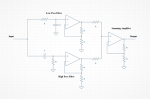
notch filter schematic
The Notch filter circuit is a very simple and easy-to-understand circuit. The only complex part of the circuit is the op-amp. Check out my article on operational amplifiers to get the schematic diagram of an operational amplifier.
notch filter cutoff frequency
The cutoff frequency is the parameter using which one can analyze a filter. In general, the cutoff frequency of a notch filter refers to the frequency of the narrowband which needs to be blocked through the filter. It is an important parameter for designing the notch filter circuit.
- The HF cut-off of the LPF: fL = 1 / ( 2 * RLP * CLP * π)
- The LF cut-off of the HPF: fH = 1 / ( 2 * RHP * CHP * π)
notch filter bandwidth || bandwidth of notch filter
Notch filters have very narrow bandwidth. Also, it is the reason why a notch filter is made out of a band-reject filter. The sharpness is depended on the Q of the notch. Normal band reject filter has a wider bandwidth than the notch filter. It is another important parameter for designing the filter. Bandwidth is also associated with the performance parameter of the filter.
notch filter bode plot || notch filter frequency response || notch filter response
Bode plot of a filter refers to the graphical representation of frequency response. Let us find out the response of a notch filter. The following plot describes the depth, bandwidth of a signal after it passes through a notch filter. It is an important parameter to determine the accuracy of the notch filter.
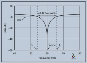
lc notch filter design
A notch filter can be designed using inductor and capacitor also. It will be a passive filter as it has no active component like operational amplifiers. The design procedure is given in the notch filter design article. Check it out here. The notch filter circuit diagram is given below.
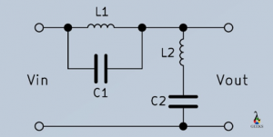
notch filter ic
Notch filter can be designed inside an Integrated Circuit. There are plenty of ICs available in market which functions like notch filter. One of the commonly used IC is the LTC1059. The pin diagram of the IC is given below.
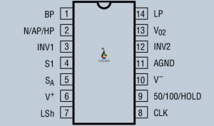
60hz notch filter
As the name suggest, a 60 Hz filter attenuates 60 Hz of frequency. The filtering is done using a notch filter because notch filter provides a sharp depth. 60 Hz filters are so popular because it is the supply frequency of USA. Other countries like India has a frequency supply frequency of 50 Hz. That is why 50 Hz filters are also used to remove supply interference. These types of filters are mainly used in ECG, EEG machines (the details are given in the Notch filter Design article).
60hz notch filter circuit
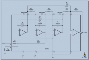
The 60 Hz notch filter is designed using several op amp. Some of them are to realise the Low pass filter, some of them to realise the high pass filter. The IC UAF42 is used to get rid of such complicated circuit. The value of registers and capacitors are given within the circuit diagram. While designing the circuit, make sure you use the exact value of the resistor and capacitors to get a more accurate result. The 60 hz notch filter circuit is given below.
rf notch filter circuit
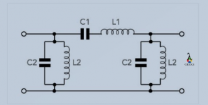
Radio Frequency notch filter has several applications. The circuit is designed using the inductors and capacitors only. At first, one capacitor and one inductor is placed in parallel. Then a set of capacitor and inductor are placed in series with the previous connection. Then another pair of inductor and capacitor (Values are equal to the first used set) are placed in parallel, in series with the second connection. The circuit is given below.
audio notch filter design || audio notch filter circuit
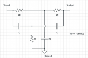
Audio notch filter is a very important filter for audio engineering. Notch filters removes the spike and noises to make the audio better. The circuit diagram of a basic audio notch filter is given below. As we can see, the circuit can be designed using passive elements like – resistors and capacitors. The generalised values of them are also given. As the circuit is passive one, there is no amplification part.
audio notch filter schematic
A schematic diagram is something which is represented by basic elements. The audio notch filter has quite a simple design. As we can see in the circuit, it is already drawn with basic elements. You can still try to simplify the circuit.
digital notch filter transfer function
Transfer function is an important expression in control system engineering. It is referred as the mathematical expression which provides output for every set of input. The following expression gives the transfer function of a digital notch filter –

Different Types of Notch Filters
low pass notch filter
Notch filters are made up of both high pass and low pass filters. Low pass filters allow the lower frequency band of a signal. Notch filters allow a narrow band of frequency resisting other bands. If the wz< wp, it is common to pass notch type. (Check the transfer function derivation in the other article to understand).
high pass notch filter
As mentioned earlier, Notch filters come with both the high pass and low pass filters. High pass filters allow the higher frequency band of a signal. A notch filter can allow any narrow band of the signal. So, if a notch filter is designed to pass a narrow band of the high-frequency component, then the filter can be said a high pass notch filter. If the wz> wp, it is a high pass notch type. (Check the transfer function derivation in the other article to understand).
2.4 ghz notch filter
We have seen notch filters are useful in minimizing interferences. Radar systems use a wide range of signals. These signals are transmitted towards various places from the air. Now, there are several electronics equipment and appliances which work on different frequency levels. Therefore, there is a high probability that the signals might get interfered among each other.
A 2.4 GHz is designed to omit or eliminate such kinds of interferences and provide a smoother service.
quarter wave stub notch filter
Quarter wave stub has several applications. If a quarter wave stub is left with an open end, it can be used as a notch filter, attenuating a certain frequency band. That is how the purpose of a notch filter is served. It is one of the important types of filter for research and development purpose. It has several other applications also.
optical notch filter
There are also notch filters in Optics. Unlike an electronics notch filter, the optical notch filter blocks a specific wavelength of light and allows the other wavelength to pass smoothly. As notch filters work for narrow bandwidth, the optical notch filter can have 10 nm. Optical notch has a lot of variety. The applications depends on the need of the notch filter.
532 notch filter || 532 nm notch filter
532 notch filter represents 532 nm optical notch filter. This optical filter is named so because it can block the light component of 532 nm wavelength and allow all other wavelengths. These filters have applications in scientific researches.
785 nm notch filter
785 notch filter represents 785 nm optical notch filter. This optical filter is named so because it can block the light component of 785 nm wavelength and allow all other wavelengths. Just like 53nm optical notch, it has also applications in scientific researches and applications.
multi notch filter
Multi-notch filters are a kind of variable notch filter for optics. In optics, notch filters are also used where we can eliminate a certain wavelength. A multi-notch filter can block multiple wavelengths at once.
holographic notch filter
A holographic Notch Filter or HNF is one type of optical notch filter. These kinds of filters can give a high laser attenuation for narrower bandwidth. HNF has application in Laser Spectroscopy.
laser notch filter
As one can guess, Laser Notch Filter is a kind of Optical Notch Filter. Laser filters are used to block a certain wavelength of laser light. There is various kind of laser notch filter available in the market. They are useful for laser-based Raman devices and Biomedical systems.
notch filter raman spectroscopy
Let us understand what Raman spectroscopy is. It is a chemical analysis that can provide us very detailed info on chemical structure. Raman spectroscopy comes into the picture when there is an interaction of light with any chemical particle.
To realize Raman Spectroscopy, a light source is needed as well as a spectrometer. Now, light is emitted from the start and caught in the spectrometer. To remove the unwanted lights, the optical notch filter is used.
2nd order notch filter || second order notch filter
In general, a filter is called a second-order filter when it has one more RC network along with a first-order network. A notch filter is a 2nd order filter as it comes with a low pass filter and a cascaded connection of a high pass filter. 2nd order notch filter has cut-off frequencies. Sallen Key feature topology is used to make higher
fliege notch filter
Fliege notch filter is another notch filter topology. There are several advantages of this topology over the twin T notch filter. First, the center frequency can be tuned using only the four precision components, i.e., two resistors and two capacitors.
One of the great features of the topology is that if there any slight mismatch, the center frequency gets affected, but the depth of the filter remains the same.
The Q of the filter can also be adjusted using two independent resistors.
fpv notch filter
These refer to 433/1.3 GHz notch filters which can filter out interference in the 1.2- 1.3 GHz frequency band if the filter is used in the 433 MHZ RC transmitter.
dc notch filter
There are several dc notches filters available. One of the most widely used applications is the GPS notch filter. The notch filter helps to eliminate interference and receive the satellite signal.
helical notch filter
Let us know what a helical filter is. A helical filter is made of a series of cavities that are further magnetically coupled. These filters provide a high Q and great performance.
Now a Helical filter can be turned into a notch filter if one of the taps of the helix is being attached to the transmission line. The depth of the notch filter will be around thirty to forty dB.
tinnitus notch filter
At first, let us know what Tinnitus is. Tinnitus is a hearing problem. If one experiences a buzzing or ringing noise in one or both o his/her ear(s), then the syndrome is called Tinnitus.
As a remedy to it, conventional hearing aids are suggested by doctors. But it is recently observed that if a notch filter is added for the tinnitus frequency, the mechanism will improve and help the recovery process.
bridged t notch filter
A bridged t notch filter is quite a different type of filter. The filter provides a shallow depth and also comes with a frequency band that is wider than the available notch filter. It is used where a need for equalization is there. It is also not considered an active filter.
microwave notch filter
A dual-drive Mach-Zander modulator achieves a microwave Notch Filter. It is efficient, and the frequency can be adjusted. Therefore, it has a higher value of the frequency band.

Hi, I am Sudipta Roy. I have done B. Tech in Electronics. I am an electronics enthusiast and am currently devoted to the field of Electronics and Communications. I have a keen interest in exploring modern technologies such as AI & Machine Learning. My writings are devoted to providing accurate and updated data to all learners. Helping someone in gaining knowledge gives me immense pleasure.
Let’s connect through LinkedIn –