Understanding Impedance Voltage: A Comprehensive Guide

what is impedance voltage

Impedance voltage is a crucial concept in electrical and electronic engineering, as it represents the opposition that a circuit or a component presents to the flow of electric current. This opposition includes both resistive and reactive components, and it plays a vital role in the performance and efficiency of electronic systems. In this comprehensive guide, we will delve into the intricacies of impedance voltage, its mathematical representation, its impact on AC circuits, and the various methods used to measure it.

What is Impedance Voltage?

Impedance voltage, denoted as Z, is the measure of the total opposition to the flow of electric current in a circuit or a component. It is expressed as a complex number, Z = R + jX, where R represents the resistive component and X represents the reactive component. The unit of impedance is the ohm (Ω).

The magnitude of the impedance, |Z|, is equal to the maximum value of the potential difference or voltage (V) across the circuit, divided by the maximum value of the current (I) through the circuit, as shown in the equation:

|Z| = V / I

The reciprocal of the impedance, 1/Z, is called the admittance and is expressed in terms of the unit of conductance, the mho unit (ohm spelled backward).

Impedance in AC Circuits
what is impedance voltage

In AC (Alternating Current) circuits, impedance becomes a dynamic player, as it accounts for the phase differences between current and voltage. This phase difference is caused by the reactive components, such as capacitance and inductance, which introduce a time delay in the current flow.

The relationship between impedance, resistance, and reactance in an AC circuit can be expressed as:

Z = √(R^2 + X^2)

where R is the resistance and X is the reactance.

The phase angle, θ, between the voltage and current is given by:

θ = tan^-1(X/R)

Understanding how impedance varies with frequency is crucial in applications such as filters, oscillators, power systems, and signal integrity analysis.

Capacitive and Inductive Impedance

The basic electrical reactive elements are capacitance and inductance, both of which have an impedance that depends on the frequency of the applied signal.

Capacitive Impedance

The impedance of an ideal capacitor is given by:

Zc = 1 / (2πfC)

where f is the frequency and C is the capacitance. As the frequency increases, the capacitive impedance decreases, and vice versa.

Inductive Impedance

The impedance of an ideal inductor is given by:

ZL = 2πfL

where f is the frequency and L is the inductance. As the frequency increases, the inductive impedance increases, and vice versa.

In practical circuits, such as PCBs or electrical components, the dielectric material between the trace and reference plane can impact the capacitance, and the physical dimensions of the electrical element, its distance to the current return path, and the electrical characteristics of the materials used can contribute to parasitic capacitances and inductances, leading to the voltage-current relationship.

Measuring Impedance

Accurately measuring impedance is crucial for ensuring efficient circuit operation, avoiding unnecessary power losses, and preventing potential issues arising from impedance mismatches. Several methods are available for measuring impedance, each with its own characteristics and applications:

  1. Bridge Method: This method uses a balanced bridge circuit to measure the impedance of a component or a circuit.
  2. I-V Method: This method directly measures the voltage and current to calculate the impedance.
  3. RF I-V Method: This method is specifically designed for measuring impedance at radio frequencies (RF).
  4. Automatically Balanced Bridge Method: This method automatically balances the bridge circuit to measure the impedance.

The choice of measurement method depends on factors such as the frequency range, the type of circuit or component, and the desired accuracy and precision.

Importance of Impedance in Electronics Design

Impedance is not just a theoretical concept but a practical tool that directly influences the performance and efficiency of electronic systems. Its measurement and control are vital in design, troubleshooting, safety, and efficiency.

In electronics design, impedance is an important parameter as it determines how components or interconnections modify the signal. Inductor impedance, for example, originates from the physical dimensions of the electrical element, its distance to the current return path, and the electrical characteristics of the materials used. All of these contribute to parasitic capacitances and inductances, which lead to the voltage-current relationship.

Proper impedance matching is crucial in various applications, such as transmission lines, filters, and power systems, to ensure efficient power transfer and minimize signal reflections and distortions.

Conclusion

Impedance voltage is a fundamental concept in electrical and electronic engineering, representing the opposition to the flow of electric current in a circuit or a component. Understanding the principles of impedance, its mathematical representation, and its behavior in AC circuits is essential for designing and analyzing efficient electronic systems.

By mastering the concepts of impedance voltage, engineers can optimize circuit performance, minimize power losses, and prevent potential issues arising from impedance mismatches. This comprehensive guide has provided a detailed overview of the topic, equipping you with the knowledge and tools necessary to navigate the complexities of impedance voltage in your electronic design and troubleshooting endeavors.

References:

  1. Electrical impedance – Wikipedia: https://en.wikipedia.org/wiki/Electrical_impedance
  2. Impedance Analysis – Basics: https://www.ceb.cam.ac.uk/research/groups/rg-eme/Edu/impedance-analysis-basics
  3. How to Measure Impedance: 5 Easy Steps for Engineers: https://saving.em.keysight.com/en/used/knowledge/guides/how-to-measure-impedance
  4. Electrical impedance | Definition, Symbol, Units, & Facts – Britannica: https://www.britannica.com/science/electrical-impedance
  5. Everything You Need To Know About Impedance: https://resources.altium.com/p/know-impedance

What Symbol Represents a Diode in Electrical Schematics: A Comprehensive Guide

what symbol represents a diode in electrical schematics a comprehensive guide

In the world of electrical and electronic circuits, the diode is a fundamental component that plays a crucial role in various applications. Diodes are two-terminal electronic devices that allow the flow of current in one direction while blocking it in the opposite direction. Understanding the symbol used to represent a diode in electrical schematics is … Read more

Is it possible to replace traditional bulbs with LEDs in any fixture? A Comprehensive Guide with Measurable and Quantifiable Data

is it possible to replace traditional bulbs with leds in any fixture a comprehensive guide

When considering replacing traditional bulbs with LEDs in any fixture, it is essential to understand the technical specifications, benefits, and potential challenges associated with this transition. This comprehensive guide provides measurable and quantifiable data to help you make an informed decision. 1. Energy Efficiency LED bulbs are renowned for their exceptional energy efficiency, consuming 75-80% … Read more

Can Two Signals Have the Same Frequency Spectrum but Different Time Domain Representations? Exploring the Relationship

can two signals have the same frequency spectrum but different time domain representations exploring the relationship

Summary The phenomenon of two signals having the same frequency spectrum but different time domain representations is known as time-frequency duality. This concept is crucial in understanding signal processing and communication systems, where signals are often modulated in frequency while maintaining their time domain characteristics. By exploring the mathematical relationships and practical examples, this comprehensive … Read more

Fan-in and Fan-out: Implications Explained for Beginners

fan in and fan out implicationsexplained for beginners

Fan-in and fan-out are fundamental concepts in digital electronics and circuitry, particularly in the design of logic gates and other digital components. These concepts are crucial for understanding the behavior and limitations of digital systems. In this comprehensive guide, we will delve into the details of fan-in and fan-out, providing a thorough explanation for beginners. … Read more

Is Adiabatic Process Reversible:Why,How And Detailed Facts

Capture

An adiabatic process may or may not be reversible. For an adiabatic process to be reversible it must satisfy few other conditions.

An adiabatic process can be reversible, however all adiabatic processes are not reversible by default. Before we come to reversible adiabatic process, we must first understand the factors that decide reversibility or irreversibility of a system in thermodynamics.

A reversible process in thermodynamics can be defined as the one, which can be retracted back to its initial stage and in doing the same no residual change or hysteresis is left either in the system or the surroundings.  A reversible process occurs in a state of quasi-equilibrium; i.e. the system is always at equilibrium with its surroundings.

A reversible process has an efficiency of 100%. This implies, the energy required to carry out the state change is minimum and there is no loss of energy to the surrounding as heat. In other words, in a reversible process the work done is maximum for the amount of energy provided as an input. This type of process is an ideal process where there is no friction.

Is Adiabatic Process Reversible?
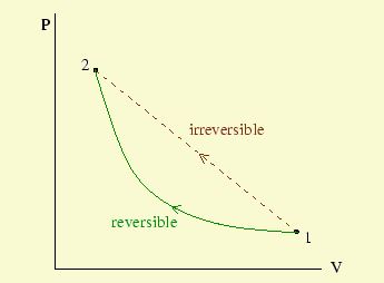
Reversible and Irreversible Process;Image Credit: theory.physics.manchester.

As shown in the picture above, while moving from point 1 to point 2, the reversible shall always be at equilibrium with its surroundings, while for an irreversible process the same is not so. Because of this characteristic, a reversible process is carried out infinitesimally slowly.

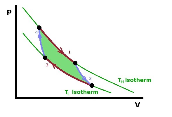
A cyclic reversible process is depicted by the theoretical carnot cycle. The theoretical carnot cycle is defined by two steps each of isothermal and adiabatic processes. The red lines in the figure below 

Carnot cycle
Carnot Cycle; Image credit: users.aber.ac.uk

indicate the isothermal steps and the blue lines denotes the adiabatic steps.

Another aspect of a thermodynamic process is Entropy, which defines the reversibility or irreversibility of a process. The delta change in entropy or randomness of a system and surroundings remains constant in an isothermal process; whereas the  irreversibility of a process is characterised by increase in the total entropy.

How Adiabatic Process Can Be Reversible?

An adiabatic process is defined by dQ=0, where Q is the amount of heat transferred between the system and surroundings.

An adiabatic process is an ideal process which is perfectly insulated from the surroundings and no heat transfer between the system and the surroundings can take place. Adiabacity of a process doesn’t qualify it to be called reversible as well.

An adiabatic process is reversible if it is isoentropic as well. In other words, there is no change in entropy.If a process is adiabatic i.e if the system has adiabatic walls and PdV work is done on the system, there is no exchange of heat with the surrounding and entropy change in this case is zero.

What is the Difference Between Reversible And Irreversible Adiabatic Process?

The reversible and irreversible adiabatic process is differentiated by change in entropy of the process.

A reversible process is an idealized process involving ideal gas in ideal conditions.When a process change takes place reversibly, the process can be retracted back to its initial stage and while doing the same, no hysteresis is left either in the system or the surroundings.

A reversible process occurs infinitesimally slowly and each step is in equilibrium with other. This is also called quasi-static. There is no change in entropy of the process in a reversible process. An idealized reversible adiabatic process does not exist in nature and cannot be achieved experimentally.

An example of a reversible adiabatic process is adiabatic expansion of a real gas.

Irreversible process on the other hand is the changes occurring in real life. An adiabatic irreversible process involves change that takes place with increase in entropy of the system. An example of an irreversible adiabatic process is free expansion of an ideal gas in a cylinder which is perfectly insulated as shown in the figure below.

Capture
Free Expansion of a Gas within a System; Image Credit: www.careerride.com

This is also an idealised thought experiment, wherein an ideal gas is kept in a cylinder with adiabatic walls having a partition, the other side of which is kept in vacuum. The gas is allowed to expand by making a hole in the partition. Since the gas is expanding into vacuum, there is no external pressure to act against and hence the work done is zero.

Thus from the first law of thermodynamics, since both dQ and dW are zero, the internal energy change dU is also zero. In case of an ideal gas, internal energy depends only on temperature and since the net change in internal energy is zero, the temperature also remains constant. Now at constant temperature, the entropy is proportional to volume and since volume increase, so does the entropy. 

How do you know if a process is Reversible or Irreversible?

Reversible processes are idealized and theoretically thought off processes in order create a comparison with actual processes, all of which are irreversible. All the processes that occur naturally have some amount of irreversibility in them.

For a process to be reversible the change must be at equilibrium with the preceding step or the change must be infinitesimally small. Such processes are called quasi-static and they require infinite time to be carried out. The work done in a reversible process is maximum possible.

Another aspect of a reversibility of irreversibility of a process is the measure of its entropy. Idealised reversible processes are isoentropic or the dS = 0 for the system and the surroundings.

Since, reversible processes are idealized cases with maximum efficiency; the amount of irreversibility is reflected in the reduced efficiency of a process from its ideal behaviour. Lower the irreversibility, higher its efficiency.

Some examples of reversible processes are frictionless movement,current flow with zero resistance (superconductivity), mixing of two samples of the same substance at same state.

Some perfectly irreversible processes are what we see in our day to day like birth or death or a bomb explosion. Others include movement of a vehicle on road, lighting a bulb, cooking food etc.

Work Done in Reversible Adiabatic Process

Since reversible adiabatic process is a ideal process, the work done is calculated based on ideal gas consideration.

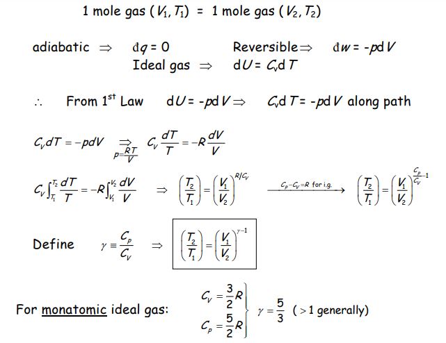
The work done expression is thus derived by considering expansion or compression of 1 mole of an ideal gas from Condition (P1, V1) to condition (P2, V2).

The work done for an adiabatic process, is shown by following PV diagram

Capture 1 1
Work Done In Reversible process; Image Credit: biological-engineering

For adiabatic consideration, dQ= 0 and for Reversible consideration dW= -pdV

For an ideal gas,

Internal energy, dU= CvdT

Capture 3

Therefore from 1st law of thermodynamics,

dU = -pdV

CvdT= -pdV

For an ideal gas 1 mole,

Capture 2

Please click to learn more on real gas examples.

Can a Zener Diode Bounce Back from a Transient Voltage Spike?

can a zener diode bounce back from a transient voltage spike

Zener diodes are widely used in electronic circuits for voltage regulation and transient voltage suppression. Understanding their behavior under transient voltage spikes is crucial for ensuring reliable circuit operation. This comprehensive guide delves into the technical details of how Zener diodes respond to and recover from such voltage spikes. Understanding Zener Diode Characteristics Zener Voltage … Read more

Advantages of Low Power Logic Design: A Comprehensive Guide

advantages of low power logic design

Low power logic design offers several key advantages, including reduced power consumption, increased battery life, improved reliability, and economic benefits. These advantages can be quantified and analyzed in detail to provide a comprehensive understanding of the benefits of low power design techniques. Reduced Power Consumption One of the primary advantages of low power logic design … Read more

How To Calculate Shear Stress: Process,Formula,Example And Exhaustive FACTS

How to Calculate Shear Stress

Shear Stress in a Pin

When it comes to calculating shear stress in a pin, it is essential to understand the concept of shear stress and its significance in mechanical engineering. Shear stress is the force per unit area that acts parallel to the surface of an object, causing it to deform. In the case of a pin, shear stress refers to the internal resistance experienced by the pin when subjected to a shearing force.

To calculate shear stress in a pin, you can use the formula:

Shear Stress = Shearing Force / Area

The shearing force is the force applied perpendicular to the pin’s axis, while the area represents the cross-sectional area of the pin. By dividing the shearing force by the pin’s cross-sectional area, you can determine the shear stress exerted on the pin.

Shear Stress in a Cylinder

Calculating shear stress in a cylinder involves understanding the behavior of materials under shear forces. In a cylinder, shear stress refers to the internal resistance experienced by the material when subjected to a shearing force.

To calculate shear stress in a cylinder, you can use the formula:

Shear Stress = Shearing Force / (2 * π * Radius * Height)

The shearing force is the force applied perpendicular to the axis of the cylinder, while the radius represents the distance from the center of the cylinder to its outer surface. The height refers to the length of the cylinder along its axis. By dividing the shearing force by the product of 2π, the radius, and the height, you can determine the shear stress exerted on the cylinder.

Shear Stress of a Shaft

The shear stress of a shaft is an important parameter to consider when designing mechanical systems. It refers to the internal resistance experienced by the shaft when subjected to a shearing force.

To calculate shear stress in a shaft, you can use the formula:

Shear Stress = Torque * Radius / Moment of Inertia

The torque represents the twisting force applied to the shaft, while the radius refers to the distance from the center of the shaft to its outer surface. The moment of inertia represents the shaft’s resistance to rotational motion and can be calculated based on the shaft’s geometry. By multiplying the torque by the radius and dividing it by the moment of inertia, you can determine the shear stress exerted on the shaft.

Measurement of Shear Stress

Measuring shear stress accurately is crucial for understanding the behavior of materials and ensuring the structural integrity of various components. There are several methods available for measuring shear stress, depending on the specific application and requirements.

One common method is the use of shear stress sensors or transducers. These devices are designed to measure the shear stress directly by converting it into an electrical signal. Shear stress sensors can be integrated into test setups or embedded within structures to monitor shear stress in real-time.

Another method involves using strain gauges. These gauges are bonded to the surface of the material and measure the strain caused by the shear stress. By analyzing the strain data, the shear stress can be calculated using mathematical models and calibration techniques.

Shear Stress in a Beam

Calculating shear stress in a beam is essential for understanding its structural behavior and ensuring its safety under load. Shear stress in a beam refers to the internal resistance experienced by the beam when subjected to a shearing force.

To calculate shear stress in a beam, you can use the formula:

Shear Stress = Shear Force / (Beam Width * Beam Height)

The shear force represents the force applied perpendicular to the beam’s longitudinal axis, while the beam width and height refer to the dimensions of the beam’s cross-section. By dividing the shear force by the product of the beam width and height, you can determine the shear stress exerted on the beam.

Shear Stress at Pipe Wall

Understanding the shear stress at the pipe wall is crucial for designing and analyzing fluid flow systems. Shear stress at the pipe wall refers to the frictional force per unit area between the fluid and the pipe wall.

To calculate shear stress at the pipe wall, you can use the formula:

Shear Stress = (4 * Fluid Viscosity * Fluid Velocity) / Pipe Diameter

The fluid viscosity represents the resistance of the fluid to flow, while the fluid velocity refers to the speed at which the fluid flows through the pipe. The pipe diameter represents the inner diameter of the pipe. By multiplying the product of 4, the fluid viscosity, and the fluid velocity by the reciprocal of the pipe diameter, you can determine the shear stress at the pipe wall.

Shear Stress from Flow

Calculating shear stress from flow is essential for understanding the behavior of fluids and their interaction with solid surfaces. Shear stress from flow refers to the force per unit area that acts parallel to the surface of an object due to the flow of a fluid.

To calculate shear stress from flow, you can use the formula:

Shear Stress = (Fluid Density * Fluid Velocity^2) / 2

The fluid density represents the mass per unit volume of the fluid, while the fluid velocity refers to the speed at which the fluid flows. By multiplying the product of the fluid density and the square of the fluid velocity by 1/2, you can determine the shear stress exerted by the fluid.

Shear Stress in a Tube

Calculating shear stress in a tube is crucial for understanding the behavior of fluid flow within the tube and designing efficient fluid transport systems. Shear stress in a tube refers to the internal resistance experienced by the fluid when flowing through the tube.

To calculate shear stress in a tube, you can use the formula:

Shear Stress = (4 * Fluid Viscosity * Fluid Velocity) / Tube Diameter

The fluid viscosity represents the resistance of the fluid to flow, while the fluid velocity refers to the speed at which the fluid flows through the tube. The tube diameter represents the inner diameter of the tube. By multiplying the product of 4, the fluid viscosity, and the fluid velocity by the reciprocal of the tube diameter, you can determine the shear stress exerted on the fluid within the tube.

In conclusion, calculating shear stress is essential for understanding the behavior of materials and fluids under shearing forces. By using the appropriate formulas and understanding the specific parameters involved, engineers can accurately determine shear stress in various components and systems. This knowledge is crucial for designing safe and efficient structures and ensuring the reliability of mechanical systems.

Shear Stress in a Plate

J. Shear Stress on a Bolt

When it comes to calculating shear stress, it’s important to understand how it applies to different objects and materials. One common scenario where shear stress is relevant is when considering the shear stress on a bolt. Bolts are often used to hold materials together, and understanding the shear stress they experience is crucial for ensuring their structural integrity.

Shear stress on a bolt is the force per unit area that acts parallel to the cross-sectional area of the bolt. It occurs when two forces act in opposite directions, causing the bolt to experience a shearing force. This shearing force can lead to deformation or failure of the bolt if it exceeds the material‘s shear strength.

To calculate the shear stress on a bolt, you need to know the force applied and the cross-sectional area of the bolt. The formula for shear stress is:

Shear Stress = Force / Area

Let’s break down the steps to calculate shear stress on a bolt:

  1. Determine the force acting on the bolt. This could be the result of external loads or the tension in the bolt due to tightening.

  2. Measure the cross-sectional area of the bolt. This can be done by measuring the diameter of the bolt and using the formula for the area of a circle (Area = π * (diameter/2)^2).

  3. Plug the values into the shear stress formula and calculate the shear stress.

It’s important to note that shear stress is typically measured in units of pressure, such as pascals (Pa) or pounds per square inch (psi). These units represent the force per unit area and allow for easy comparison between different materials and scenarios.

By calculating the shear stress on a bolt, engineers and designers can ensure that the bolt can withstand the forces it will experience in its intended application. This knowledge is crucial for maintaining the safety and reliability of structures and machinery.

In summary, shear stress on a bolt is the force per unit area that acts parallel to the cross-sectional area of the bolt. It can be calculated by dividing the force applied by the cross-sectional area of the bolt. By understanding and calculating shear stress, engineers can make informed decisions about the design and use of bolts in various applications.

Frequently Asked Questions

How to calculate shear stress in a pin?

stress concentration
gif

To calculate shear stress in a pin, you can use the formula: shear stress = force / area. Determine the force acting on the pin and divide it by the cross-sectional area of the pin to obtain the shear stress.

How to calculate shear stress in a cylinder?

To calculate shear stress in a cylinder, you can use the formula: shear stress = force / area. Determine the force acting on the cylinder and divide it by the surface area of the cylinder to obtain the shear stress.

How to calculate shear stress of a shaft?

To calculate shear stress of a shaft, you can use the formula: shear stress = torque * radius / polar moment of inertia. Multiply the torque applied to the shaft by the radius and divide it by the polar moment of inertia to obtain the shear stress.

How to measure shear stress?

Shear stress can be measured using various methods such as strain gauges, rheometers, or viscometers. These instruments measure the deformation or flow of a material under shear forces, allowing the calculation of shear stress.

How to calculate shear stress in a beam?

gif

To calculate shear stress in a beam, you can use the formula: shear stress = shear force / cross-sectional area. Determine the shear force acting on the beam and divide it by the cross-sectional area to obtain the shear stress.

How to calculate shear stress at pipe wall?

To calculate shear stress at the pipe wall, you can use the formula: shear stress = shear force / circumference. Determine the shear force acting on the pipe and divide it by the circumference of the pipe to obtain the shear stress.

How to calculate shear stress from flow?

gif

To calculate shear stress from flow, you can use the formula: shear stress = viscosity * velocity gradient. Multiply the viscosity of the fluid by the velocity gradient to obtain the shear stress.

How to calculate shear stress in a tube?

gif

To calculate shear stress in a tube, you can use the formula: shear stress = shear force / inner surface area. Determine the shear force acting on the tube and divide it by the inner surface area to obtain the shear stress.

How to calculate shear stress in a plate?

To calculate shear stress in a plate, you can use the formula: shear stress = shear force / plate thickness. Determine the shear force acting on the plate and divide it by the thickness of the plate to obtain the shear stress.

How to calculate shear stress on a bolt?

gif

To calculate shear stress on a bolt, you can use the formula: shear stress = force / shear area. Determine the force acting on the bolt and divide it by the shear area of the bolt to obtain the shear stress.