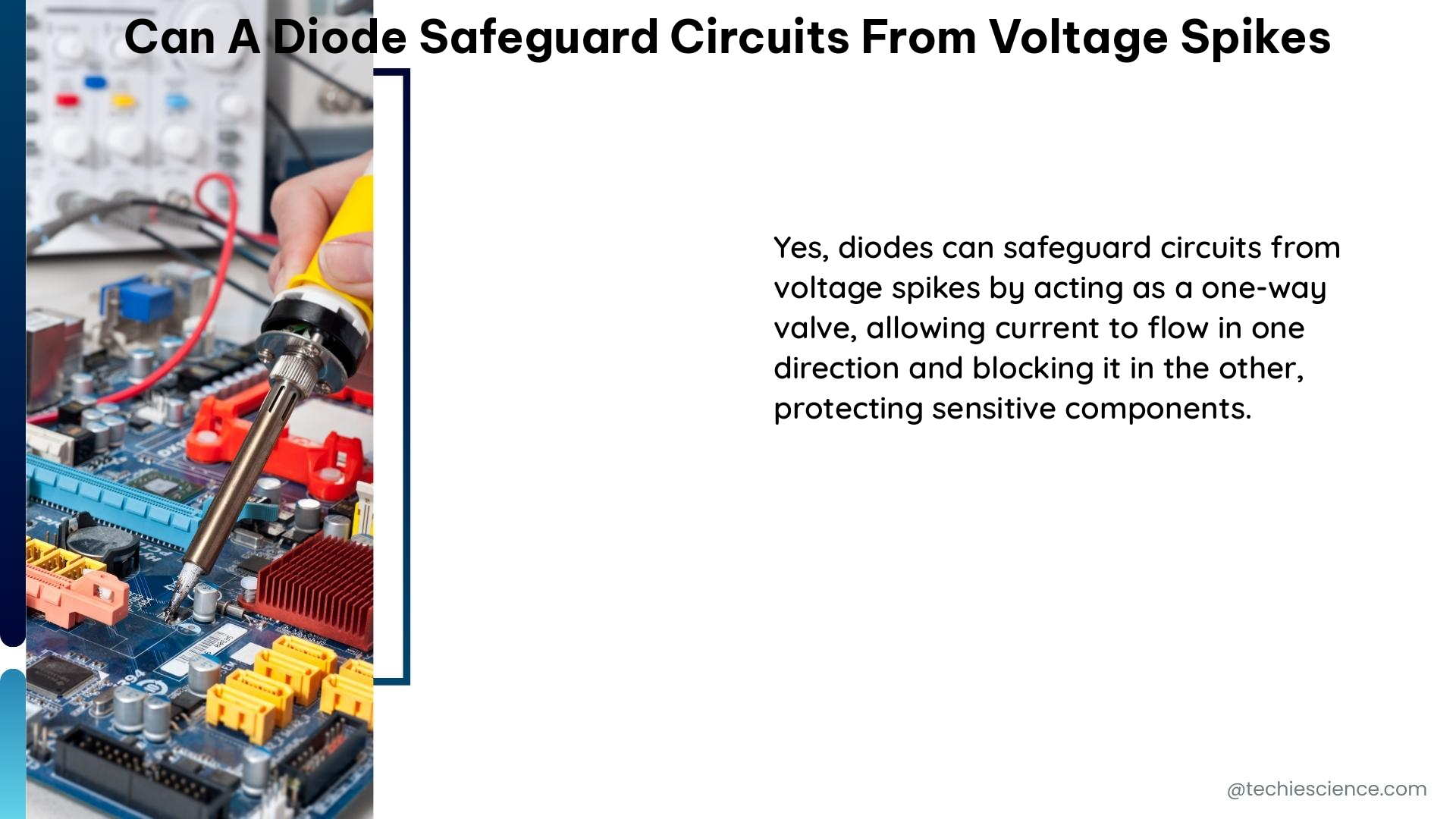
A circuit is a closed path that may contain several different electrical circuit elements, and a circuit can be series, parallel, or a combination of both series and parallel.
This article will discuss the series circuit function, definition, advantages, and disadvantages, etc.
Series Circuit Definition
A circuit can be a series, parallel, or combination of both series or parallel circuits.
A series circuit combination is when every electric current element is connected from one terminal to another component’s terminal in such a way that there is only one way for the current to flow.
Series Circuit Function
There is the following essential function of a series circuit:
- In series, circuit current through each circuit element is identical regardless of the resistance or impedance of the components connected in the circuit.
- The voltage drop across each circuit element can vary with the value of resistance, impedance, or electrical characteristics of each circuit element.
- The total voltage drop in the overall series circuit is equal to the summation of the voltage drop across the individual component of the series circuit combination.
- When more than one resistor, capacitor, inductor, or voltage source are linked in a series combination that can be replaced by one equivalent value of resistor, inductor, capacitor or voltage source, respectively.
- The total power dissipated in the series circuit combination is amounting to the summation of individual power dissipated by each circuit element in the series circuit.
- The series circuit is also known as the voltage divider circuit. The potential drop across any circuit element is the function of the total voltage applied across the overall series circuit.
Voltage in a Series Circuit
In a series circuit combination, the overall circuit voltage is split between the different series circuit elements.
If there is ‘n’ number of components is connected in a series circuit and V1, V2, V3 …..Vn is the individual voltage across each element of the series circuit, then the total voltage (V) across the series circuit can be defined as:
V =V1 + V2+ V3 …..+ Vn
The overall voltage in a series circuit is the summation of individual voltage across each electrical circuit element. The voltage across each electric component depends upon the electrical property of the respective element.
Current in a Series Circuit
The overall current of a series circuit has the same magnitude as the current across each circuit component.
If there is ‘n’ number of electrical components and I1, I2, I3 … In, is the current through each component then the total current (I):
I = I1 = I2 = I3 …= In
The series circuit has a constant current magnitude in each part of the circuit; that is, the magnitude of the current is identical in every aspect of a series circuit.
Series Circuit Working
There is only one path in which the electric current can flow through in a series circuit as all the electrical components in the series circuit are linked in a single path.
In a series circuit, the magnitude of the current is the same throughout the circuit. In contrast, the overall series circuit voltage gets divided between the several components of the circuit respectively.
In a series circuit, as the current passes through different components connected in a single path, each component has an identical current magnitude through it, which is also equal to the overall current in the circuit. In contrast, the voltage gets divided across each component in the series combination. A potential drop happens when the electrical potential energy gets converted into another form of energy by any electrical component. Hence, the potential drop depends on the energy conversion property of each element.
Series Circuit Configuration
Any series circuit can be a combination of essential elements such as diode, capacitor, resistor, inductor, etc.
Let’s take a circuit of series configuration as given below
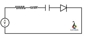
There is a series combination of one resistor, one inductor, a capacitor, and one diode is connected in a series combination with a voltage source in the above circuit.
Series Circuit Formula
the series circuit combination of more than one resistor, capacitor, and the inductor can be replaced by one equivalent value of the resistor, capacitor, inductor, respectively.
For Series Resistance
To calculate the total for overall resistance in a series circuit combination of n number of resistors, use the formula:
Re = R1+ R2 + R3 ……+Rn
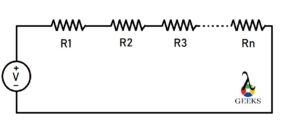
Where Re is the equivalent or total resistance of the series combination and R1, R2, R3 … Rn are the resistance of individual resistors connected in series circuit combination of ‘n’ numbers of resistors.
For Series Capacitors
To calculate the total or overall capacitance of a series circuit combination consists of n number of capacitor use of formula:


where Ce is the equivalent of the total capacitance of the series circuit combination and C1, C2, C3 … Cn are the capacitance of individual capacitors connected in a series circuit combination of ‘n’ number of capacitor.
For Series Inductor
Use this formula to calculate the total or overall inductance of a series circuit combination consisting of n number of inductors:
Le = L1 + L2+ L3 …..+ Ln
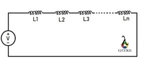
Where Le is the equivalent of the total inductance of the series circuit combination and L1, L2, L3 … Ln are the inductance of individual inductors connected in the series circuit.
Series Circuit Advantages
Different advantages of the series circuit over parallel circuit are as follows:
- In a series circuit, each circuit element has the identical current magnitude passing through it.
- Voltage sources of any magnitude can be linked together in a series combination.
- Overall voltage can be increased in series circuit easily.
- In this series circuit, switching on or off of all the appliances together or devices can be done with only one switch.
- Series circuit combination does not get overheated easily.
- Series circuit has a straightforward design.
Series Circuit Disadvantages
As advantages of the series circuit discussed above, let’s now discuss the drawbacks of any series circuit as follows:
- Any fault or break in any component in the series circuit will affect the overall circuit.
- Faulty components or parts cannot be identified easily as they are connected in series with each other.
- The current sources with different magnitudes cannot be connected in series with each other.
- All components connected in series have a single switch to turn on or turn off; they cannot be operated separately.
- The voltage drop(or potential drop) across each series circuit component may different from each other.
FAQ:
What is the purpose of a Series Circuit?
A series circuit can combine different circuit elements in a single path or branch of the circuitry.
A series circuit can be used where only one path is required between two points. The current through any series circuit is controlled as the magnitude of current remains the same throughout.
Is Current the same in Series?
Series circuit is known as voltage divider circuit as the voltage gets splited into all of its circuit components.
As there is only one path for the electric current to flow through, so the magnitude of the current remains the same throughout the circuit.
What is the Series Circuit in Electricity?
Series circuit is a type of closed path circuit, which can be a combination of several different electric components.
The series circuit can be defined as when the terminal of one circuit element is connected to the other terminal of the following circuit element in such a way that there is only one path for current to flow through.
