Contents: Cantilever Beam
- Cantilever Beam Definition
- Cantilever Beam Free Body diagram
- Cantilever Beam Boundary conditions
- Determine the internal shear and Bending moment in the cantilevered beam as a function of x
- Finding Shear force and Bending Moment acting at a distance of 2 m from the free end on a Cantilever beam with Uniformly Distributed load (U.D.L.)
- The equation of the deflection curve for a cantilever beam with Uniformly Distributed Loading
- Cantilever beam Stiffness and vibration
- Cantilever beam bending due to pure bending moment inducing Bending Stress
- Finding Cantilever Bending Stress induced due to Uniformly Distributed load (U.D.L.)
- Question and Answer on Cantilever beam
Cantilever Beam Definition
https://en.wikipedia.org/wiki/Cantilever
A cantilever beam is a beam whose one end is fixed, and another end is free. The fixed support prevents the displacement and rotational motion of the beam at that end. Cantilever beam permits the overhanging feature without any additional support. When the load is applied to the free end of the beam, the cantilever transmits that load to the support where it applies the shear force [V] and the bending Moment [B.M.] at the fixed end.
Cantilever beam free body diagram
Consider a cantilever beam with point load acting on the free end of the beam.
The Free body diagram for the cantilever beam is drawn below:

Cantilever beam boundary conditions
The reaction Forces and moment at A can be calculated by applying Equilibrium conditions of
\\sum F_y=0, \\sum F_x=0 ,\\sum M_A=0
For horizontal Equilibrium
\\sum F_x=0
R_{HA}=0For vertical Equilibrium
\\sum F_y=0
\\\\R_{VA}-W=0
\\\\R_{VA}=W
Taking Moment about A, Clockwise moment positive and Counter Clockwise moment is taken as negative
WL-M_A=0
M_A=WL
Determine the internal shear and Bending moment in the cantilevered beam as a function of x
Consider the Cantilever beam with Uniformly distributed loading shown in the Figure below.
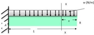
The resultant load acting on the Beam Due to U.D.L. can be given by
W = Area of a rectangle
W = L * w
W=wL
Equivalent Point Load wL will act at the centre of the beam. i.e., at L/2
Free Body Diagram of the Beam becomes

The value of the reaction at A can be calculated by applying Equilibrium conditions
\\sum F_y=0, \\sum F_x=0 ,\\sum M_A=0
For horizontal Equilibrium
\\sum F_x=0
\\\\R_{HA}=0
For vertical Equilibrium
\\sum F_y=0
\\\\R_{VA}-wL=0
\\\\R_{VA}=wL
Taking Moment about A, Clockwise moment positive and Counter Clockwise moment is taken as negative
wL*\\frac{L}{2}-M_A=0
\\\\M_A=\\frac{wL^2}{2}
Let X-X be the section of interest at a distance of x from a free end
According to the Sign convention discussed earlier, if we start calculating Shear Force from the Left side or Left end of the beam, Upward acting force is taken as Positive, and Downward acting Force is taken as Negative.
Shear force at A is
S.F_A=R_{VA}=wLat region X-X is
S.F_x=R_{VA}-w[L-x]
\\\\S.F_x=wL-wL+wx=wx
Shear force at B is
S.F=R_{VA}-wL
\\\\S.F_B=wL-wL=0
The shear Force values at A and B states that the Shear force varies linearly from fixed end to free end.
For BMD , if we start calculating Bending Moment from the Left side or Left end of the beam, Clockwise Moment is taken as Positive and Counter-Clockwise Moment is taken as Negative.
B.M at A
B.M_A=M_A=\\frac{wL^2}{2}B.M at X
B.M_x=M_A-w[L-x]
\\\\B.M_x=\\frac{wL^2}{2}-\\frac{w(L-x)^2}{2}
\\\\B.M_x=wx(L-\\frac{x}{2})B.M at B
B.M_B=M_A-\\frac{wL^2}{2}
\\\\B.M_B=\\frac{wL^2}{2}-\\frac{wL^2}{2}=0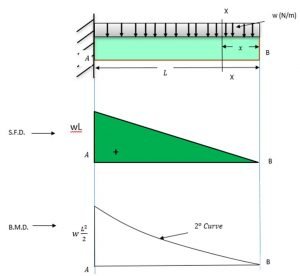
Finding Shear force and Bending Moment acting at a distance of 2 m from the free end on a Cantilever beam with Uniformly Distributed load (U.D.L.)
Consider the Cantilever beam with uniformly distributed loading shown in the Figure below. w = 20 N/m only. L = 10 m, x = 2 m
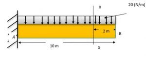
The resultant load acting on the Beam Due to U.D.L. can be given by
W = Area of a rectangle
W = 20*10
W=200 N
Equivalent Point Load wL will act at the centre of the beam. i.e., at L/2
Free Body Diagram of the Beam becomes,

The value of the reaction at A can be calculated by applying Equilibrium conditions
\\sum F_y=0, \\sum F_x=0 ,\\sum M_A=0
For horizontal Equilibrium
\\sum F_x=0
\\\\R_{HA}=0
For vertical Equilibrium
\\sum F_y=0
\\\\R_{VA}-wL=0
\\\\R_{VA}=200 N
Taking Moment about A, Clockwise moment positive and Counter Clockwise moment is taken as negative
200*\\frac{10}{2}-M_A=0
\\\\M_A=1000 \\;N-m
Let X-X be the section of interest at a distance of x from a free end
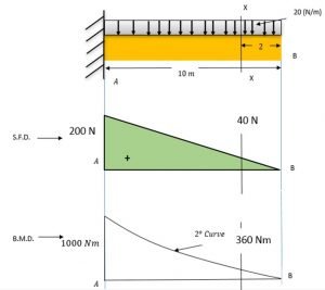
According to the Sign convention discussed earlier, if we start calculating Shear Force from the Left side or Left end of the beam, Upward acting force is taken as Positive, and Downward acting Force is taken as Negative.
Shear force at A is
S.F_A=R_{VA}=wL
\\\\S.F_A=200 N
at region X-X is
S.F_x=R_{VA}-w[L-x]
\\\\S.F_x=wL-wL+wx=wx
for x = 2 m
\\\\S.F_x=wx=20*2=40\\;N
Shear force at B is
S.F=R_{VA}-wL
\\\\S.F_B=wL-wL=0
The shear Force values at A and B states that the Shear force varies linearly from fixed end to free end.
For BMD , if we start calculating Bending Moment from the Left side or Left end of the beam, Clockwise Moment is taken as Positive and Counter-Clockwise Moment is taken as Negative.
B.M at A
B.M_A=M_A
B.M_A=1000\\;N.m
B.M at X
B.M_x=M_A-w[L-x]
\\\\B.M_x=\\frac{wL^2}{2}-\\frac{w(L-x)^2}{2}=wx[L-\\frac{x}{2}]\\\\B.M_x=20*2*[10-\\frac{2}{2}]=360\\;N.mB.M at B
B.M_B=M_A-\\frac{wL^2}{2}=1000-\\frac{20*10^2}{2}=0
The equation of the deflection curve for a cantilever beam with Uniformly Distributed Loading
Consider the Cantilever beam of length L shown in the Figure below with Uniformly distributed load. We will derive the equation for slope and deflection for this beam using the Double integration method.
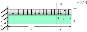
The bending moment acting at the distance x from the left end can be obtained as:
M=-wx* \\frac{x}{2}Using the differential equation of the curve,
\\frac{d^2y}{dx^2}=M = \\frac{-wx^2}{2}Integrating once we get,
EI \\frac{dy}{dx}= \\frac{-wx^3}{6}+C_1………..[1]Integrating equation [1] we get,
EIy= \\frac{-wx^4}{24}+C_1 x+C_2……..[2]The constants of integrations can be obtained by using the boundary conditions,
At x = L, dy/dx = 0; since support at A resists motions. Thus, from equation [1], we get,
C_1=\\frac{wL^3}{6}At x = L, y = 0, No deflection at the support or fixed end A Thus, from equation [2], we get,
0= \\frac{-wL^4}{24}+\\frac{wL^3}{6} *L+C_2C_2= \\frac{-wL^4}{8}Substituting the constant’s value in [1] and [2] we get new sets of equation as
EI \\frac{dy}{dx}= \\frac{-wx^3}{6}+\\frac{wL^3}{6}………..[3]EIy= \\frac{-wx^4}{24}+\\frac{wL^3}{6} -\\frac{wL^4}{8}……..[4]Evaluate slope at x = 12 m and maximum deflection from given data: I = 722 cm4 , E = 210 GPa, L =20 m, w = 20 N-m
From the above equations: at x = 12 m,
EI \\frac{dy}{dx}= \\frac{-wx^3}{6}+\\frac{wL^3}{6}210*10^9*722*10^{-8}* \\frac{dy}{dx}= \\frac{-20*12^3}{6}+\\frac{20*20^3}{6}\\frac{dy}{dx}=0.01378 \\;radiansFrom equation [4]
EIy= \\frac{-wx^4}{24}+\\frac{wL^3}{6} -\\frac{wL^4}{8}210*10^9*722*10^{-8}*y= \\frac{-20*12^4}{24}+\\frac{20*20^3}{6} -\\frac{20*20^4}{8}y=-0.064 \\;m
Cantilever beam Stiffness and vibration
Stiffness can be defined as the resistance to bending deflection or deformation to bending moment. The ratio of the maximum load applied to the maximum deflection of a beam can be called the stiffness of the beam.
For a cantilever beam with a Force W at the free end, the maximum deflection is given by
δ=\\frac{WL^3}{3EI}Where W = applied load, L = length of the beam, E = young’s Modulus, I = the second Moment of Inertia
Stiffness is given by,
k=W/δ
\\\\k=W/\\frac{WL^3}{3EI}
\\\\k=\\frac{3EI}{L^3} The natural frequency can be defined as the frequency at which a system tends to vibrate in the absence of any driving or resisting force.
ω_n=\\sqrt{k/m}
\\\\ω_n=\\sqrt{\\frac{3EI}{L^3m} }
Where m = mass of the beam.
Cantilever beam bending due to pure bending Moment inducing Bending Stress
When a member is subjected to equal and opposite couples in the member’s plane, it is defined as pure bending. In pure bending Shear force acting on the beam is zero.
Assumptions: Material is Homogenous
Hook’s Law is applicable
Member is prismatic
A couple is applied in the plane of the member
No warping of the cross-section of the beam takes place after bending
Strain profile must be linear from the neutral axis
The stress distribution is linear from the neutral axis to the top and bottom fibres of the beam.
Euler-Bernoulli’s Equation for Bending Moment is given by
\\frac{M}{I}=\\frac{\\sigma_b}{y}=\\frac{E}{R}M = Applied bending moment over the cross-section of the beam.
I = Second area moment of Inertia
σ = Bending Stress-induced in the member
y = Vertical distance between the neutral axis of the beam and the desired fibre or element in mm
E = Young’s Modulus in MPa
R = Radius of Curvature in mm
Bending Stress for cantilever beam with diameter d, and applied load W can be given as,
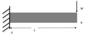
Bending Stress will be acting at the fixed support of the beam
The moment applied M = W.L.
Second Area moment of Inertia
I=\\frac{\\pi}{64}d^4The vertical distance between the neutral axis of the beam and the desired fiber or element
y=d/2
Bending Stress is given as
σ=\\frac{My}{I}
\\\\σ=\\frac{32WL}{\\pi d^3}Finding Bending Stress acting on Cantilever beam with Uniformly Distributed load (U.D.L.)
Consider A Cantilever beam with Uniformly distributed loading shown in the Figure below has I = 722 cm4 , E = 210 GPa, L =20 m, w = 20 N-m

The reaction Forces and moment at A can be calculated by applying Equilibrium conditions of
\\sum F_y=0, \\sum F_x=0 ,\\sum M_A=0
For horizontal Equilibrium
\\sum F_x=0
\\\\R_{HA}=0
For vertical Equilibrium
\\sum F_y=0
\\\\R_{VA}-wL=0
\\\\R_{VA}=200 N
Taking Moment about A, Clockwise moment positive and Counter Clockwise moment is taken as negative
200*\\frac{10}{2}-M_A=0
\\\\M_A=1000 \\;N-m
Bending Stress
σ=\\frac{My}{I}
σ=\\frac{1000*50*10^{-3}}{2*722*10^{-8}}
σ=3.238\\;MPa
Question and Answer on Cantilever beam
Q.1 What is the ratio of Maximum load applied to maximum deflection of a beam called?
Ans: Stiffness can be defined as the resistance to bending deflection or deformation to bending moment. The ratio of the maximum load applied to the maximum deflection of a beam can be called the stiffness of the beam.
Q.2 Define a cantilever beam?
Ans: A cantilever beam is a beam whose one end is fixed, and the other end is free. The fixed support prevents the displacement and rotational motion of the beam at that end. Cantilever beam permits the overhanging feature without any additional support. When the load is applied to the free end of the beam, the cantilever transmits that load to the support where it applies the shear force [V] and the bending Moment [B.M.] towards the fixed end.
Q.3 A cantilever beam is subjected to uniformly distributed load over the length of the beam, what will be the shape of Shear Force and Bending Moment diagram?
Ans: For a cantilever beam subjected to uniformly distributed load over the beam’s length, the Shear force diagram’s shape will be a linear curve and Bending Moment diagram will be a Parabolic curve.
Q.4 A cantilever is subjected to uniformly Varying load over the length of the beam starting at zero from a free end, what will be the shape of Shear Force and Bending Moment diagram?
Ans: For a cantilever beam subjected to uniformly varying load over the beam’s length, the Shear force diagram’s shape will be Parabolic curve and Bending Moment diagram will be a cubic or third-degree curve.
Q.5 Where do tension and compression act in bending of cantilever beams?
Ans: For a cantilever beam of a given span, the maximum bending stress will be at the beam’s Fixed end. For downward netload, maximum tensile bending stress is acted on top of cross-section, and max compressive Stress is acted on the bottom fibre of the beam.
Q.6 A cantilever is subjected to Moment (M) over the length of the beam, what will be the Shear force and Bending Moment?
Ans: For a cantilever beam subjected to moment M over the beam’s length, the Shear force will be zero, since no external bending force will be acting on the beam and Bending moment will remain constant for the entire length of the beam.
To know about Strength of material(click here)and Bending Moment Diagram Click here

I am Hakimuddin Bawangaonwala , A Mechanical Design Engineer with Expertise in Mechanical Design and Development. I have Completed M. Tech in Design Engineering and has 2.5 years of Research Experience. Till now Published Two research papers on Hard Turning and Finite Element Analysis of Heat Treatment Fixtures. My Area of Interest is Machine Design, Strength of Material, Heat Transfer, Thermal Engineering etc. Proficient in CATIA and ANSYS Software for CAD and CAE. Apart from Research.