Contents: Bending Moment
- Bending Moment Definition
- Bending Moment Equation
- Relation between load intensity, Shear Force and Bending Moment
- Unit for Bending Moment
- Bending Moment of a Beam
- Bending Moment Sign Convention
- Shear Force and Bending Moment Diagram
- Types of Supports and Loads
- Question and Answer
Bending Moment Definition
In solid body mechanics, a bending moment is a reaction induced inside a structural member when an external force or moment is applied to it, causing the member to bend. The foremost, standard, and simplest structural member subjected to bending moments is that beam. If the moment applied to the beam tries to bend the beam in the plane of the member, then it is called a bending moment. In the case of Simple bending, If the Bending moment is applied over a particular Cross-section, the stresses Developed are called Flexural or Bending stress. It varies linearly from the neutral axis over the cross-section of the beam.
Bending Moment Equation
The Algebraic sum of the moments over a particular cross-section of the beam due to clock or anticlockwise moments is called bending moment at that point.
Let W be a force vector acting at a point A in a body. The moment of this force about a reference point (O) is defined as
M = W x p
Where M = Moment vector, p = the position vector from the reference point (O) to the point of application of the force A. The symbol indicates the vector cross product. it is easy to compute the moment of the force about an axis that passes through the reference point O. If the unit vector along the axis is ”i”, the moment of the force about the axis is defined as
M = i . (W x p)
Where [.]represent Dot product of a vector.
The Mathematical Relation between load intensity, Shear Force and Bending Moment
Relations: Let f = load intensity
Q = Shear Force
M = Bending Moment
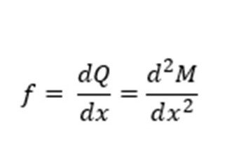
The rate of change of shear force will give the intensity of the distributed load.
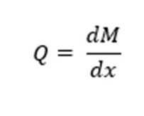
The rate of change of bending moment will give shear force at that point only.

Unit for Bending Moment
Bending moment has a unit similar to the couple as Nm.
Bending Moment of a Beam
Assuming a Beam AB having a certain length subjected to Bending Moment M, If the Top fiber of the beam, i.e., above the neutral axis, is in compression, then it is called Positive Bending Moment or Sagging Bending moment. Similarly, If the Top fiber of the beam, i.e., above the neutral axis, is in tension, it is called the Negative Bending Moment or Hogging Bending moment.

Bending Moment Sign Convention
There is a Specific Sign convention followed while determining Maximum Bending-moment and Drawing and BMDs.
- If we start calculating Bending-Moment from the right side or right end of the beam, Clockwise Moment is taken as negative, and Counter-wise Moment is taken as Positive.
- If we start calculating Bending-Moment from the Left side or Left end of the beam, Clockwise Moment is taken as Positive, and Counter Clockwise Moment is taken as Negative.
- If we start calculating Shear Force from the right side or right end of the beam, Upward acting force is taken as Negative, and Downward acting Force is taken as Positive.
- If we start calculating Shear Force from the Left side or Left end of the beam, Upward acting force is taken as Positive, and Downward acting Force is taken as Negative.
Shear Force and Bending Moment Diagram
Shear Force is the Algebraic sum of forces Parallel to cross-section over a particular cross-section of the beam due to action and reaction forces. Shear Force tries to shear off the beam’s Cross section perpendicular to the beam’s axis, and due to this, the developed shear stress distribution is Parabolic from the neutral axis of the beam. Bending moment is a sum of the moments over a particular cross-section of the beam due to Clockwise and Counter Clockwise Moments. This tries to bend the beam in the plane of the member, and due to transmission of it over a cross-section of the beam, the Developed Bending stress distribution is Linear from the neutral axis of the beam.
Shear Force Diagram is the Graphical representation of the variation of Shear Force Over the cross-section along the length of the beam. With the Shear Force Diagram’s help, we can identify Critical sections Subjected to Shear and design amendments to be made to avoid failure.
Similarly, Bending Moment Diagram is the Graphical representation of the Bending moment’s variation over the cross-section along the length of the beam. With the B. M Diagram’s help, we can identify Critical sections Subjected to bending and design amendments to be made to avoid failure. While constructing the Shear Force Diagram [S.F.D.], There is a sudden rise or sudden drop due to point load acting on the beam while constructing Bending moment Diagram [BMD]; there is a sudden rise or sudden drop due to couples acting on the beam.
Types of Supports and Loads
Fixed Support: It can offer three reactions in the plane of the member (1 Horizontal reaction, 1 Vertical reaction, 1 Moment reaction)
Pin Support: It can offer two reactions in the plane of the member (1 Horizontal reaction, 1 Vertical reaction)
Roller Support: It can offer only one reaction in the plane of the member (1 Vertical reaction)
Concentrated or point Load: In this, the entire intensity of load is restricted to a finite area or on a point.
Uniformly Distributed Load [U.D.L.]: In this, the entire intensity of load is constant along the length of the beam.
Uniformly varying Load [U.V.L.]: In this, the entire intensity of load is varying linearly along the length of the beam.

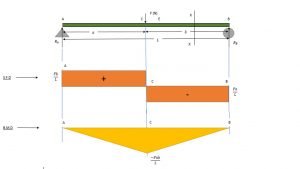
Shear Force Diagram and Bending Moment Diagram for a simply supported beam carrying point load only.
Consider the simply supported beam shown in the figure below carrying Point loads only. In a Simply supported beam, one end is pin supported while another end is roller support.

The value of the reaction at A and B can be calculated by applying Equilibrium conditions of

For vertical Equilibrium,
![]()
Taking Moment about A, Clockwise moment positive and Counter Clockwise moment is taken negative
![]()
![]()
Putting the value of RB in [1], we get
![]()
![]()


Let X-X be the section of interest at a distance of x from end A
According to the Sign convention discussed earlier, if we start calculating Shear Force from the Left side or Left end of the beam, Upward acting force is taken as Positive, and Downward acting Force is taken as Negative.
Shear Force at Point A
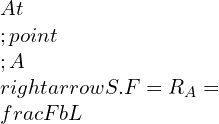
We know that the Shear Force remains constant between points of application of Point Loads.
Shear force at C
![]()
Shear force at region X-X is
![]()
![]()
![]()
![]()
Shear Force at B
![]()
For Bending Moment Diagram, if we start calculating B.M from the Left side or Left end of the beam, Clockwise Moment is taken as positive. Counter Clockwise Moment is taken as Negative.
- at A = 0
- at B = 0
- at C
![]()
![]()
![]()
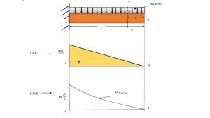
Shear Force [S.F.D] and Bending Moment Diagram [B.M.D] for a Cantilever beam with Uniformly Distributed load (U.D.L.) only.
Consider the Cantilever beam shown in the figure below U.D.L. only. In a Cantilever beam, one end is Fixed while another end is free to move.
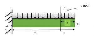
The resultant load acting on the Beam Due to U.D.L. can be given by
W = Area of a rectangle
W = L * w
W=wL
Equivalent Point Load wL will act at the center of the beam. i.e., at L/2
Free Body Diagram of the Beam becomes

The value of the reaction at A can be calculated by applying Equilibrium conditions

For horizontal Equilibrium
![]()
![]()
For vertical Equilibrium
![]()
![]()
![]()
Taking Moment about A, Clockwise moment positive and Counter Clockwise moment is taken as negative
![]()
![]()
Let X-X be the section of interest at a distance of x from a free end
According to the Sign convention discussed earlier, if we start calculating Shear Force from the Left side or Left end of the beam, Upward acting force is taken as Positive, and Downward acting Force is taken as Negative.
Shear force at A is
![]()
at region X-X is
![]()
![]()
Shear force at B is
![]()
![]()
The shear Force values at A and B states that the Shear force varies linearly from fixed end to free end.
For BMD , if we start calculating Bending Moment from the Left side or Left end of the beam, Clockwise Moment is taken as Positive and Counter-Clockwise Moment is taken as Negative.
B.M at A
![]()
B.M at X
![]()

![]()
B.M at B
![]()

4 Point Bending Moment Diagram and Equations
Consider a simply supported beam with two equal Loads W acting at a distance a from either end.

The value of the reaction at A and B can be calculated by applying Equilibrium conditions

For vertical Equilibrium
![]()
Taking Moment about A, Clockwise moment positive and Counter Clockwise moment is taken negative
![]()
![]()
From [ 1 ]we get
![]()
According to the Sign convention discussed earlier, if we start calculating Shear Force from the Left side or Left end of the beam, Upward acting force is taken as Positive, and Downward acting Force is taken as Negative. For BMD diagram plotting, if we start calculating Bending Moment from the Left side or Left end of the beam, Clockwise Moment is taken as Positive and Counter-Clockwise Moment is taken as Negative.
Shear force at A is
![]()
Shear force at C is
![]()
Shear force at D is
![]()
Shear force at B is
![]()
For Bending Moment Diagram
B. M at A = 0
B. M at C
![]()
![]()
B.M at D
![]()
![]()
B. M at B = 0

Question and Answer of Bending Moment
Q.1) What is the difference between moment and bending moment?
Ans: A Moment can be defined as the product of force and the length of the line passing through the point of support and is perpendicular to the force. A bending moment is a reaction induced inside a structural member when an external force or moment is applied to it, causing the member to bend.
Q.2) What is a bending moment diagram definition?
Ans: Bending Moment Diagram is the Graphical representation of the variation of B.M Over the cross-section along the length of the beam. With this Diagram’s help, we can identify Critical sections Subjected to bending and design amendments to be made to avoid failure.
Q.3) What is the Formula for Bending Stress?
Ans: Bending Stress can be defined as resistance induced due to Bending Moment or by two equal and opposite couples in the plane of the member. Its Formula is given by

Where, M = Applied bending moment over the cross-section of the beam.
I = Second area moment of Inertia
σ = Bending Stress-induced in the member
y = Vertical distance between the neutral axis of the beam and the desired fiber or element in mm
E = Young’s Modulus in MPa
R = Radius of Curvature in mm
To know about Strength of material click here

I am Hakimuddin Bawangaonwala , A Mechanical Design Engineer with Expertise in Mechanical Design and Development. I have Completed M. Tech in Design Engineering and has 2.5 years of Research Experience. Till now Published Two research papers on Hard Turning and Finite Element Analysis of Heat Treatment Fixtures. My Area of Interest is Machine Design, Strength of Material, Heat Transfer, Thermal Engineering etc. Proficient in CATIA and ANSYS Software for CAD and CAE. Apart from Research.