Shear Strain: 31 Facts You Should Know

Shear strain Shear velocity 300x300 1

What is shear strain?

Shear strain is the ratio of change in dimensions to the original dimension due to shear stress and deformation perpendicular rather than parallel to it. Shear strain results from the use of 2 parallel and opposite forces working at the surfaces of an object.

Shear strain formula:

Shear strain=ΔxL0/L.

Shear Modulus:

“This is the constant of proportion and is well-defined by the ratio of stress to strain.”

Shear modulus is generally represented by S.

S=shear-stress. / shear-strain.

Shear strain units:

This is dimensionless quantity, so this is Unitless.

Shear strain symbol:

Shear strain symbol=γ or ε

Shear strain unit:

1, or radian

Shear strain from axial strain

Strain:

Applied loads or displacements lead to change in dimensions. For the uniaxial displacement, the axial strain defined basically as the ratio of the variation in length to the actual length.

Shear stress strain diagram

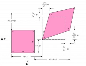
The three-dimensional strain components may also be represented as simple axial strains and shear-strains. The displacement vectors (u,v,w) acting along the axes (x,y,z) respectively.
deformation 1
Image credit : Wikipedia

The uniaxial strain in x-direction due to displacement gradient,

1 3

Similarly, the shear-strain in the y-direction due to displacement gradient is given by,

2 3

The shear-strain components are represented as strain matrix as following,

4 1

Three shear-strains are the strains represented in all planes in x,y,z directions as XY, YZ, XZ.

The strains are represented in the strain matrix-induced due to the stress:

5 1

Strain Measurement:

It is difficult to measure stress directly. So, the strain measurement can be done using electric resistance circuit gauges connected to it.

Strain gauge measurement | Shear strain from a strain gauge

The strain gauge measurement is used to determine the resistance of the wire foiled together to the conducting substrate. The wire resistance is R,

\\frac{\\Delta R}{R}= K.\\varepsilon

where K recognized as strain-factor

Alternatively,

\\varepsilon= deformation = strain

so, strain can be induced by using strain measurement.

Since the strains are low, the Wheatstone bridge needs to determine the resistances. The galvanometer reading has to be zero to find out the resistances R1, R2, R3, R4. More than one configuration can be used to measure the strain. A half wiring can be used and attached to the other gauges. There are one active meter and one dummy meter. The dummy gauge reduces the temperature effects by canceling out them. Such difference can lead to an improvement in the accuracy of the circuits.

Maximum shear strain equation:

Maximum normal strain (εmax.)

(εx+εy)/2+(((εx-εy)/2)2+(γxy/2)2)0.5.

Minimum normal strain (εmin).

(εx+εy)/2-(((εx-εy)/2)2+(γxy/2)2)0.5.

Maximum shear-strain (in-plane) ( γmax (in-plane)).

((εx-εy)2+(γxy)2)0.5

Principal angle (θp)

[atan(γxy/(εx-εy))]/2

Principal shear strain:

Principal Stress:

Shear stress is zero at an alignment then principal stress happens.

Principal Angle:

This is the angle of alignment in that principal stress will occur for a definite point.

Principal Strain:

This is the highest and least normal strain possible for an material at that specific point and shear-strain is zero at the angle where principal strain occurs.

The 3 stresses normal to principal shear plane are termed principal-stress, where as in a plane where shear-strain is zero is termed as principal-strain.

Pure shear strain:

principal stress and strain are zero.

What is shear strain energy ?

Strain energy due to shear stress | Shear strain energy theory:

Maximum shear strain energy | Distortion energy (Von Mises) theory

The failure of utmost ductile material could have been determined by the shear stress theories or Von Mises theory as the failure occurs at the shearing of the materials. This theory can be represented as

(σ1−σ2)2+(σ2−σ3)2+(σ3−σ1)2=2σy2=constant

For  σ3 = 0,

The yield locus is an ellipse similar to sheer diagonal. In3D Stress system, this equation states the surface of a prism with circular cross section. More precisely a cylinder with its central axis along the line σ1 = σ2 = σ3.

The axis cut-thru the principal stress’s origin, and it is inclined at equal angle. when σ3 = 0,

The failure condition for ellipse formed by the intersection of the (σ1, σ2) plane with the inclined cylinder.

Shear strain energy per unit volume theory.

As per von Mises theory in 3D,the yield locus will be at the surface of the inclined cylinder. Points inside the cylinder show the safe points, whereas the points outside the cylinder show the failure conditions. The cylinder axis along σ1 = σ2 = σ3 line termed the hydrostatic stress line. It shows that the hydrostatic stress alone cannot give yield. It considers all the conditions altogether and shows that all cylinder points are safe.

Shear strain example problems

  • metal cutting
  • painting brush
  • Chewing gum
  • In river water case, river bed will experience the shear stress because of water flow situations.
  • During screen-sliding circumstance.
  • To Polishing a surface.
  • To write on surface, will experience shear-strain.

The following image of rectangular hut shows the deformation of rectangular into parallelogram due to shear-strain.

The reason behind shear strain:

Shear stress is the applied force that will cause deformation of a material by slippage along a plane or a plane parallel to the stress imposed on the surface of the object.

Relationship between shear stress and strain

Shear strain vs shear stress | shear strain vs shear force

The shear strain is the deformation caused due to shear stress. Shear stress is the stress occurred due to shear forces in-between the object’s parallel surfaces.

Torsional shear strain

Torsional shear-strain τ = shear stress (N/m2, Pa) T = applied torque (Nm)

The shear-strain is calculated by the angle of twist, the length, and the distance along the radius.

γ = shear strain (radians)

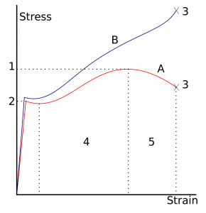
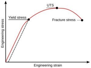
Shear stress strain curve:

Shear stress acts along the surface or parallel to the surface and may cause 1 layer to slide on others. shear stress leads to deforming the rectangular object into the parallelogram.

Shear stress acts to change the dimension and angle of the object.

Shear stress= F/A

Shear-strain: The shear-strain is the deformation amount to a given line rather than parallel.

Shear strain gamma

Shear-strain gamma= delta x/L.

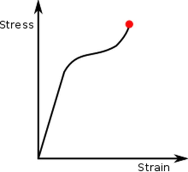
The relationship between the shear stress and shear-strain for a specific material is acknowledged as that material’s shear.

Shear stress strain curve Yield stress
Shear strain curve
Image Credit: Wikipedia

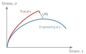
Stress Strain curve Engineering and True
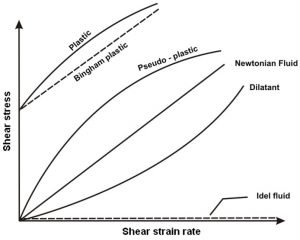
Variation of shear stress with rate of deformation
Stress strain curve 3
Image credit : nptel

Shear stress-strain curves are a significant graphical measure.

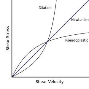
Shear Stress vs Shear velocity

Shear stress vs shear rate for dilatant and pseudoplastic non-Newtonian fluids compared to Newtonian fluid.

Shear strain Shear velocity
Image credit : DirectEON (talk) 08:46, 28 March 2008 (UTC), Dilatant-pseudoplasticCC BY-SA 3.0

Octahedral shear strain:

The octahedral shear stress/ strain gives the yield point of elastic material under a general stress state. The material displays yielding when the octahedral shear stress reach the extreme value of stress/strain. This is equivalent acknowledged as Von Mises yield criteria.

Shear strain rate :

The strain is the ratio of change in the length to its original length, so; shear-strain is a dimensionless quantity, so the strain-rate is in inversed time unit.

Shear strain formula in metal cutting:

Shear Plane Angle:

This is the angle between the horizontal plane and the shear plane, Significant for shear-strain applications in metal cutting.

The shear-strain rate at the shear plane, ϒAB is a function of cutting velocity and feed.

Difference between shear stress and Shear strain

Shear stress vs Shear strain:

Shear stress contemplates a block, which is subjected to a set of equal and opposite forces Q and this block recognized as bi-cycle-brake-block linked to wheel.There is a chance that one layer of the body slides on others, during shear stress initiation. If this failure is  not permitted, then a shear stress T will be formed.

Q – shear load shear stress (z) = area resisting shear A.

This shear stress will act on vertically to the area. The direct stresses will be at normal direction to the area of application though.

Considering bicycle brake block, the rectangular shaped blocks mightn’t be deformed after the baking force has been applied and block might change the shape in the form of strain.

The shear-strain is proportionate to the shear stress in the elastic range. The modulus of rigidity is represented as 

shear stress z shear strain y = – = constant = G

The constant G = the modulus of rigidity or shear modulus

Why do edge dislocations in crystal lattices introduce compressive tensile and shear lattice strains while screw dislocations only introduce shear strains ?

Because observational and pedagogical definition prescribes the coordinate frames in which this is true”, is probably the most accurate answer.

There are several approaches to visualizing the behavior of the strain fields around dislocations. The first approach is by direct observation; the second one borrows concepts from fracture mechanics. Both are equivalent.

  • An edge dislocation directed to the Burgers vector. Although a screw-dislocation directed perpendicularly to it.
  • The screw-dislocation ‘unzip’ the lattice as it travels thru it, creating a ‘screw’ or helical prearrangement of atom around the core.

Shear strain problems:

Problem : A rectangular block has area of 0.25m2. The height of the block is 10cm.A shearing force is applied to the top face of the block. And the displacement is 0.015mm.Find the stress, strain and shearing force. Modulus of rigidity= 2.5*10^10 N/m2

Given:

A= 0.25m2

H=10m

x=0.015mm

η =2.5*10^10N/m2.

Solution:

Shear strain = tan θ =X/H

                                   =0.015*10^-3/10*10^-2

                          tan θ =1.5*10^-3

Modulus of Rigidity = Shear stress/Shear strain

       2.5*10^10           = shear stress /0.0015

Shear stress               =2.5*10^10*1.5*10^-3

                                   =3.75*10^7 N/m2

Shear stress              =F/A

F                                = 3.75*10^7*0.25

                                  = 9.37*10^6 N.

Problem : A cube has side of 10 cm. The shearing force is applied on the upper side of the cube and the displacement is 0.75 cm by force of 0.25N. Calculate modulus of rigidity of the substance.

Given:

A= 10*10= 100 cm2

F=0.25N

H= 5cm

X=0.75cm

As we know,

Modulus of rigidity = Shear stress/Shear strain

Shear-strain is= X/H

                    =0.75/5

                    = 0.15

Shear Stress= F/A

                     = 0.25/100*10^-4

                     =25N.

Modulus of Rigidity = 25/0.15

                                   = 166.7 N/m^2

For more articles click here
Hooke’s Law: 10 Important Facts

stress strain hooks 290x300 1

What is Hooke’s Law?

Hooke’s law basic properties:

The mechanical behaviour of materials depends on their response to loads, temperature, and the environment. In several practical problems, these controlling parameters’ combined effects must be assessed. However, the individual effects of loads (elastic and plastic deformation) must be studied in detail before attempting to develop an understanding of the combined effects of load and temperature or the effects of load and environment. The material response may also depend on the nature of the loading. When the applied deformation increases continuously with time (as in a tensile test), then reversible (elastic) deformation may occur at small loads before the onset of irreversible/plastic deformation at higher loads. Under reversed loading, the material may also undergo a phenomenon known as ”fatigue.”

Hooke’s Law Definition:

Robert Hooke law 1660. It states that the material’s deformations are directly proportional to the externally applied load on the material. 

According to Hooke’s law, the material behavior elastic can be explained as the displacements occurring in the solid material due to some force. The displacement is directly proportional to the force applied.

Does Hooke’s law include proportional limits or elastic limits?

Hooke’s law tell strain of the material is proportionate to the stress applied within the elastic limit of that material.

Stress-strain curve for Hooke’s law:

Stress :

The resistance offered by the body against deformation to the applied external force to the unit area is known as stress. The force is applied while stress is induced by the material. A loaded member remains in equilibrium when the externally applied load and the force due to deformation are equal.

\\sigma =\\frac{P}{A}

Where,

\\sigma= Intensity of stress,

  • P= Externally applied load
  • A= cross-sectional area

Unit of Stress:

The unit stress depends on the unit of External force and the cross-sectional area.

Force is expressed in Newton, and Area is expressed in m^2.

The unit of stress is N/m^2.

Types of stress:

Tensile stress:

The stress induced in the body due to the stretching of the externally applied load on the material.Results in an increase in the length of the material.

Compressive stress:

The stress induced in the body due to the shortening of the material.

Shear stress:

The stress occurred in the material due to the shearing action of external force.

Strain:         

When the body is subjected to external force, there is some change in the dimension of the body.

The strain is represented as the ratio of the change in dimension of the body to that of the original dimension of the body.

\\varepsilon =\\frac{\\Delta L}{L}

Unit of Strain

The strain is a dimensionless quantity.

Types of strain:

Tensile strain: 

The tensile strain is the strain induced due to the change in length.

Volumetric strain:

The volumetric strain is the strain induced due to the change in volume.

Shear strain:

The shear strain is the strain induced due to change in the area of the body.

Hooke’s law graph | Hooke’s law experiment graph

Hooke's Law: Stress-strain curve
Image credit:[User:Slashme] (David Richfield), Stress v strain A36 2, CC BY-SA 3.0

Robert Hooke studied springs and the elasticity of the springs and discovered them. The stress-strain curve for various materials has a linear region. Within the proportionality limit, the force applied to pull any elastic object is directly proportional to the displacement of the spring extension.

From the origin to proportionality limit material follows Hook’s Law. Beyond the elastic limit, the material loses its elasticity and behaves like plastic. When the material undergoes elastic limit, After removal of the applied force, the material goes back to its original position.

According to Hookes law stress is directly proportional to strain up to elastic limit but that stress vs strain curve is linear up to proportional limit rather than elastic limit Why ?

Which of these statements is correct All elastic materials follow Hookes law or materials that follow Hookes law are elastic ?

  • Answer:

All elastic materials does not follow Hook’s law. There are some elastic materials that does does not obey Hook’s law. so the first statement is invalid. But it is not necessity that materials that follow Hook’s law are elastic, In stress-strain curve for Hook’s law materials follow Hook’s law till their proportional limit and do possess elasticity. Every material has some elastic nature at certain limit and it can store elastic energy at certain point.

What is the difference between Hookes law and Youngs modulus ?

Hooke’s law of Elasticity :

When an external force is applied to the body, the body tends to deform. If the external force is removed and the body comes back to its original position. The tendency of the body to coming back to its original position after the removal of stress is known as elasticity. The body will regain its original position after the removal of stress within a certain limit. Thus there is a limiting value of force up to which and within which the deformation disappears completely. The stress that corresponds to this limiting force is an elastic limit of the material.

Young’s modulus | Modulus of Elasticity:

The proportionality constant between the stress and strain is known as young’s modulus and modulus of elasticity.

 \\sigma =E\\varepsilon

E= Young’s Modulus

What is an example of Hooke’s law ?

Hooke’s law spring:

An important component of automobile objects , the spring stores potential elastic energy when it is stretched or compacted. The spring extension is directly proportional to the applied force within the proportionality limit.

Mathematical representation of the Hooke’s law states that the applied force is equal to the K times the displacement,

F= -Kx

Hook’s law material elastic properties can only be explained when applied force is directly proportional to the displacement.

What is the name of the substance that does not obey Hooke’s law ?

Answer : Rubber

Does Hooke’s law fails in case of thermal expansion?

Answer : No

Hooke’s law stress strain | Hooke’s law for plane strain

Hooke’s law is important to understand the behaviour of the material when it is stretched or compressed. It is important to enhance the technology by understanding the material behaviour properties.

Hooke’s law equation stress strain

F=ma

σ=F/A

ε = Δl/l0

σ = E ε

F= -k * Δx

Strain is the ratio of total deformation or change in length to the initial length.

This relationship is given by ε = Δl/l0 where strain, ε, is change in l divided by initial length , l0 .

Why do we consider a spring massless in Hooke’s law ?

Hooke’s law is dependent on the spring extension and spring constant and is independent on the mass of the spring.so we consider spring massless in Hook’s law.

Hooke’s law experiment :

The Hooke’s law experiment performed to find out the spring constant of the spring. The original length of the spring before applying load is measured. Record the applied loads (F) in N and the corresponding lengths of the spring after extension. The deformation is the new length minus the original length before loads.

Since the force has the form

 F = -kx

Why is Hooke’s law negative ?

While representing hooks law for springs, the negative sign is always presented before the product of the spring constant and the deformation even though the force is not applied. The restoring force, which gives the deformation to the spring and the spring, is already in the opposite direction to that of the applied force. Thus, it is important to mention the direction of the restoring force while solving elastic material problems.

Derivation of Hooke’s Law:

Hooke’s Law equation:

F=-kx

Where,

  • F=Applied force
  • k=Constant for displacement
  • x = Length of the object
  • The use of k is dependent on the kind of elastic material, its dimensions and its shape.
  • When we apply a relatively large amount of applied force, the material deformation is larger.
  • Although, the material remains elastic as before and returns to its original size, and when we remove the force that we apply, it retains its shape. At times,

Hooke’s law describes the force of

F = -Kx

Here, F represents the equal and oppositely applied to restore, causing the elastic materials to get back to their original dimensions.

How is Hooke’s Law measured?

Hooke’s law units

SI units: N/m or kg/s2.

Hooke’s law spring constant

We can easily understand Hooke’s Law in connection with the spring constant. Moreover, this law states that the force required for compression or extension of a spring is directly proportional to the distance to which we compress or stretch it.

In mathematical terms, we can state this as follows:

F=-Kx

Here,

F represents the force that we apply in the spring. And x represents the compression or extension of the spring, which we usually expressed in metres.

Hooke’s law example problems

Let us understand this more clearly with the following example:

It stretches a spring by 50 cm when it has a load of 10 Kg. Find its spring constant.

Here, it has the following information:

Mass (m) = 10 Kg

Displacement (x) = 50cm = 0.5m

Now, we know that,

Force= mass x acceleration

=> 10 x 0.5= 5 N.

As per the Spring Constant formula

k = F/x

=> -5/0.5= -10 N/m.

Applications of Hooke’s law | Hooke’s law application in real life

  1. It is used in Engineering applications and physics.
  2. Guitar string
  3. Manometer
  4. spring scale
  5. Bourdon tube
  6. Balance wheel

Hooke’s law experiment discussion and conclusion

Limitation of Hooke’s law:

Hooke’s law is a first-order approximation to the response of the elastic bodies. It will eventually fail once the material undergoes compression or tension beyond its certain elastic limit without some permanent deformation or change of state. Many materials vary well before reaching the elastic limits.

Hook’s law is not a universal principle. It does not apply to all the materials. It applies to the materials having elasticity. And till the material capacity to stretch to a certain point from where they won’t regain their original position.

It is applicable until the elastic limit of the material. If the material is stretched beyond the elastic limit, plastic deformation takes place in the material.

The law can give exact answers only to the material undergoing small deformations and forces.

Hooke’s law and elastic energy:

Elastic Energy is the elastic potential energy due to the stored deformation of the stretching and compression of an elastic object, such as stretching and release of the spring. According to Hook’s law, the force required is directly proportional to the amount of stretch of the spring.

Hook’s Law: F= -Kx             — (Eq1)

The force applied is directly proportional to the extension and deformation of the elastic material. Thus,

Stress is directly proportional to strain as stress is the applied force to that of unit area and strain is deformation to that of the original dimension. The stress and strain considered are normal stress and normal strain.

In shearing stress,Material must be homogeneous and isotropic within its certain proportionality limits.

Shear stress represented as,

τxy = Gγxy —(Eq2)

Where,

  • τxy=shear stress
  • G=modulus of rigidity
  • γxy=shearing strain

This relation represents Hook’s law for shear stress. It is considered for the small amount of force and deformation. Material leads to failure if applied load larger force.

Considering material subjected to shearing stresses τyz and τzy, for small stress, the γxy will be the same for both the conditions and are represented in similar ways. The shear stresses within the proportional limit,

τxy = Gγxy —(Eqn3)

τxy = Gγxy —(Eqn4)

Case1: plain strain  where the strains in the z-direction are considered to be negligible,

\\varepsilon zz=\\varepsilon yz=\\varepsilon xz=0

the stress-strain stiffness relationship for isotropic and homogeneous material represented as,

1

The stiffness matrix reduces to a simple 3×3 matrix, The compliance matrix for the plane strain is found by inverting the plane strain stiffness matrix and is given by,

2

 Case2:Plane strain:

The stress-strain stiffness matrix expressed using the shear modulus G, and the engineering shear strain

\\gamma xy=\\varepsilon xy+\\varepsilon yx=2\\varepsilon xy is represented as,

4

The compliance matrix is,

5

Hooke’s law Problems:

States Hookes Law What is the spring constant of a spring that needs a force of 3 N to be compressed from 40 cm to 35 cm.

Hook’s law:

F= -Kx ,

3= -K (35-40)

K=0.6

A force of 1 N will stretch a rubber band by 2 cm Assuming that Hookes law applies how far will a 5 N force stretch the rubber band

Force is directly proportional to the amount of the stretch, According to Hook’s law:

F= -Kx

\\frac{F1}{F2}=\\frac{x1}{x2}

  F2=3cm

For more article click here

Compressive Stress: 5 Important Facts

Compressive Stress 300x58 1

What is a compressive force?

The tensile and compressive property of the material represent the axial loads along the orthogonal axes. Loads that are stretched at the system boundaries are described as tensile loads, while those compressed at the system boundaries described as compressive loads.

The externally applied force on the body deforms the body in such a way that the body decreases in volume, and length is called compressive stress.

It is the restored strain of the body to deform when applied to external compressive load. An increase in Compressive stress to slender, long cylinders tend to undergo structural failure due to buckling of columns. When the material fails to withstand the compression, stress buckling occurs.

compressive stress
compressive stress

Compressive stress formula:

The normal force is applied to the unit area.

\sigma =\frac{F}{A}

Where,

Compressive force (F): compression force is the load required to compress the material to put the material together.

Compressive stress unit:

The SI unit of it is same as unit of the force to that of the area.

So, it is represented as N/m2 or Pa.

Dimension of Compressive stress:

Compressive stress dimension is [ML-1T-2].

Is compressive stress positive or negative?

Answer: compressive stress is negative as it is compressed since change in dimension (dL) has the opposite direction.

Are yield strength and compressive strength the same ?

Answer: No, yielding in tension and compression is not the same. Value will change as per applicability.

Compressive strength:

This is the capacity of the material to withstand the compression occur due to compressive stress. There are some materials that can withstand the only tension, some materials can withstand the only compression, and there are some materials that can withstand both tension and compression. The ultimate compressive strength is the value obtained when the material goes through its complete failure. The compression test is done the same as the tensile test. Only difference is the load used is compressive load.

Compressive strength is higher in rock and concrete.

Compressive stress of mild steel | low carbon steel:

Material that undergoes large strains before failure is ductile materials such as mild steel, aluminum and its alloys. Brittle materials, when undergoes compressive stress, the occurrence of rupture due to the sudden release of the stored energy. Whereas when the ductile material undergoes compressive stress, the material will compress, and deformation takes place without any failure.

Compressive Stress and Tensile Stress | Compressive stress vs tensile stress

  Compressive stress Tensile stress
Results of Compressive stress consequences of squeezing in the of the material. Tensile stress outcomes of stretching of the material
Push or Pull Whereas the compressive stress is the push given to body by external forces to change its shape and size. Tensile stress is the pull given to the body by external forces to change its shape and size.
Compression or elongation Compressive stress is generated from external compressive force Tensile stress is generated because of elongation force intends to stretch.
Application on Bar When bar undergoes compressive stress, strains are compressive (negative). When bar undergoes tensile stress, strains are tensile (positive).

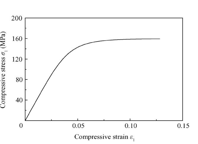
Compressive stress strain curve

Stress-strain diagram: Compression stress

Compressive stress 1
Image credit: Wei SUN et al

The stress-strain diagram for compression is different from tension.

Under compression test, the stress-strain curve is a straight line till an elastic limit. Beyond that point, a distinct bend in the curve representing the onset of plasticity; the point shows the composite compressive yield stress, which is directly related to residual stress. The increase in residual stress increases compressive stress.

In the compression test, the linear region is an elastic region following Hooke’s law. Hence the region can be represented as,

E= Young’s modulus

In this region, the material behaves elastically and returns to its original position by the removal of stress.

Yield point:

This is the point where elasticity terminates, and plasticity region initiate. So, after yield point, material will not able to return in its actual shaped after the removal of stress.

It is found if crystalline material goes through compression, the stress-strain curve is opposite to tension applications in the elastic region. The tension and compression curves vary at larger deformations (strains) as there is compression at the compressed material, and at the tension, the material undergoes plastic deformation.

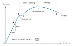
Stress-strain in tension | tensile test:

Line OA: Proportional limit

Line OA represents a proportional limit. The proportional limit is the limit till when the stress is proportionate to strain following the Hooks Law. As stress increases, the deformation of the material increases.

Point A: Elastic limit:

In this point maximum stress within a solid material has been applied. This point is called elastic limit. The material within elastic limit, will undergo deformation, and after stress removal, material will back to its actual position.

What is Elasto-plastic region?

Elasto-plastic region:

It is the region between yield point and elastic point.

Point B: Upper yield point

Plastic deformation initiates with dis-location from its crystalline structure. This displacement becomes higher after upper yield point, and it limits the movement of it,  this characteristics known known as strain hardening.

Point C: Lower yield point

This is the point after which the characteristics like strain hardening initiates. And it is observed that beyond elastic limit, the property like plastic deformation happens.

Permanent deformation:

Upper yield point:

A point at which maximum load or stress is applied to initiate plastic deformation.

The upper yield point is unstable due to crystalline dislocations movement.

Lower yield point:

The limit of min load or stress essential to preserve plastic behavior.

The lower yield point is stable as there is no movement of crystalline.

Stress is the resistance offered by the material when applied to an external load, and strain hardening is an increase in resistance slowly due to an increase of dislocations in the material.

Point D: ultimate stress point

It represents the ultimate stress point. The maximum stress can withstand the ultimate stress. After the increase of load, failure occurs.

Point E: Rupture point

It represents the breaking or rupture point. When the material undergoes rapid deformation after the ultimate stress point, it leads to failure of the material. It the maximum deformation occurred in the material.

Compressive stress example problems| Applications

  • Aerospace and Automotive Industry: Actuation tests and spring tests
  • Construction Industry: The construction industry directly depends on the compressive strength of the materials. The pillar, the roofing is built by using compressive stress.
  • Concrete pillar: In a concrete pillar, the material is squeezed together by compressive stress.
  • The material is compressed bonded, such as to avoid failure of the building. It has a sustainable amount of strained stored energy.
  • Cosmetic Industry: compaction of compact powder, eyeliners, lip balms, lipsticks, eye shadows is made by applying the compressive stress.
  • Packaging Industry: Cardboard packaging, compressed bottles, PET bottles.
  • Pharmaceutical Industry: In the pharmaceutical Industry, compressive stress is mostly used.
  • The breaking, compacting, crumbling is done in the making of tablets. The hardness and compression strength is a major part of the pharmaceutical Industry.
  • Sports industry: cricket ball, tennis ball, basketball ball are compressed to make it tougher.

How to measure compressive stress?

Compression test:

The compression test is determination of the behavior of a material under compressive load.

The Compression test is usually used for rock and concrete. Compression test gives the stress and deformation of the material. The experimental result has to validate of the theoretical findings.

Types of compression testing:

  • Flexure test
  • Spring test
  • Crushing test

Compression test is to determine the integrity and safety parameter of the material by enduring compressive stress. It also provides the safety of finished products, components, manufactured tools. It determines whether the material is fit for the purpose and manufactured accordingly.

The compression tests provide data for the following purposes:

  • To measure the batch quality
  • To understand the consistency in manufacture
  • To assist in the design procedure
  • To decrease material price
  • To guarantee international standards quality etc.

The compressive strength testing machine:

Compression testing machines comprises the measurements of material properties as Young’s modulus, ultimate compression strength, yield strength, etc., hence overall static compressive strength characteristics of materials.

The compression apparatus is configured for multiple applications. Due to machine design, it can perform tensile, cyclic, shear, flexure tests.

The compression test is operated the same as tensile testing. Only the load variation occurs in both the testing. Tensile test machines use tensile loads, whereas compression test machines use compressive loads.

Compressive strengths of various materials:

·      Compressive strength of concrete: 17Mpa-27Mpa

·      Compressive strength of steel: 25MPa

·      Granite compressive strength: 70-130MPa

·      The compressive strength of cement: 11.5 – 17.5MPa

·      The compressive yield strength of aluminum: 280MPa

What is allowable compressive stress for steel?

Answer:  The allowable stresses are commonly measured by structure codes of that metal such as steel, and aluminum. It is represented by the fraction of its yields stress (strength)

What is compressive strength of concrete at various ages?

It is the minimum compressive strength were material in standard test of 28-day-old concrete cylinder.

The concrete compressive strength measurements necessitate around 28 to 35MPa at 28 days.

Compressive Strength of Concrete:

13

Compressive stress problems:

Problem #1

A steel bar 70 mm in diameter and 3 m long is surrounded by a shell of a cast iron 7 mm thick. Calculate the compressive load for combined bar of 0.7 mm in the length of 3m. ( Esteel = 200 GPa, and Ecast iron = 100GPa.)

Solution:

δ=\frac{PL}{AE}

δ=δ cast iron=δ steel=0.7mm

δ cast iron =\frac{Pcastiron(3000)}{\frac{\pi }{4}*{<em>100 000</em>}*{84^{2}-70^{2}}} = 0.7

P cast iron = 50306.66 πN

δ steel= {\frac{Psteel(3000)}{\frac{\pi }{4}*{<em>200 000</em>}*{70^{2}}}= 0.7

P steel=57166.66πN

ΣFV=0

P= P cast iron +P steel

P=50306.66π+57166.66π

P=107473.32πN

P=337.63kN

Problem #2:

A statue weights 10KN is resting on a flat surface at the top of a 6.0m high pillar. The cross-sectional area of the tower is 0.20 m2 and it is made of granite with a mass density of 2700kg/m3. Calculate compressive stress and strain at the cross-section 3m below from the top of the tower and top segment respectively.

Solution :

The volume of the tower segment with height

H=3.0m and cross-sectional area A=0.2m2 is

V= A*H= 0.3*0.2=0.6m^3

Density ρ=2.7×10^3 kg/m3, (graphite)

Mass of tower segment

m= ρV =(2.7×10^3 *0.60m3)=1.60×10^3 kg.

The weight of the tower segment is

Wp = mg=(1.60×103*9.8)=15.68KN.

The weight of the sculpture is

Ws =10KN,

normal force 3m below the sculpture,

F⊥= wp  + ws  =(1.568+1.0)×104N=25.68KN.

Therefore, the stress is calculated by F/A

=2.568×104*0.20

=1.284×10^5Pa=128.4 kPa.

Y=4.5×10^10Pa = 4.5×10^7kPa.

So, the compressive strain calculated at that position is

Y=128.4/4.5×107

=2.85×10⁻⁶.

Problem #3:

A steel bar of changeable cross-section is endangered to axial force. Find the value of P for equilibrium.

E= 2.1*10^5MPa. L1=1000mm, L2=1500mm, L3=800mm.A1=500mm2,A2=1000mm2,A3=700mm2.

p333

From equilibrium:

{\sum Fx}= 0

+8000-10000+P-5000=0

P=7000N