How To Calculate Mass Flow Rate: From Several Entities, Problem Examples

How to Calculate Mass Flow Rate

Introduction

When it comes to fluid dynamics, understanding how to calculate mass flow rate is crucial. Mass flow rate is a fundamental concept in engineering and thermodynamics that measures the amount of mass passing through a given point in a system per unit of time. It is an essential parameter in various applications, including pipe flow, nozzle design, and flowmeter calibration.

Definition and Notation

Before diving into the calculation of mass flow rate, let’s define some key terms and notation. Mass flow rate, denoted as , is the mass of a substance flowing through a given cross-sectional area per unit of time. It is typically measured in kilograms per second (kg/s) or other mass units per time unit.

To calculate the mass flow rate, we need to consider the density of the fluid, the velocity of the fluid, and the cross-sectional area through which the fluid is flowing. The formula for mass flow rate is:

ṁ = ρ * A * V

Where:
is the mass flow rate
ρ is the density of the fluid
A is the cross-sectional area
V is the velocity of the fluid

Calculation of Mass Flow Rate

To calculate the mass flow rate, we need to know the density of the fluid, the velocity of the fluid, and the cross-sectional area. Let’s break down the steps involved in calculating the mass flow rate:

  1. Determine the density of the fluid: The density of the fluid can be obtained from reference tables or measured using specialized instruments. It is typically expressed in kilograms per cubic meter (kg/m³).

  2. Measure the velocity of the fluid: The velocity of the fluid can be measured using various techniques, such as flowmeters or pitot tubes. It is crucial to ensure accurate velocity measurements for precise mass flow rate calculations.

  3. Determine the cross-sectional area: The cross-sectional area refers to the area through which the fluid is flowing. It can be calculated using geometric formulas or measured directly using appropriate instruments.

  4. Plug the values into the formula: Once you have obtained the density, velocity, and cross-sectional area, you can plug these values into the mass flow rate formula: ṁ = ρ * A * V. Calculate the product of the density, cross-sectional area, and velocity to obtain the mass flow rate.

Importance of Accurate Measurement

Accurate measurement of mass flow rate is crucial in many engineering applications. It allows engineers to understand and control the flow of fluids in various systems. Whether it’s optimizing the performance of a chemical process or designing efficient HVAC systems, accurate mass flow rate measurement ensures proper operation and prevents potential issues.

By accurately calculating the mass flow rate, engineers can make informed decisions regarding system design, equipment sizing, and process optimization. It enables them to identify potential bottlenecks, optimize energy consumption, and ensure the safety and reliability of the system.

Factors Affecting Mass Flow Rate

Several factors can affect the mass flow rate of a fluid. Understanding these factors is essential for accurate calculations and system design. Here are some key factors that influence mass flow rate:

  1. Fluid properties: The density and viscosity of the fluid play a significant role in determining the mass flow rate. Different fluids have different densities and viscosities, which affect their flow characteristics.

  2. Cross-sectional area: The size and shape of the cross-sectional area through which the fluid is flowing directly impact the mass flow rate. A larger area allows for a higher flow rate, while a smaller area restricts the flow.

  3. Velocity: The velocity of the fluid is a critical factor in determining the mass flow rate. Higher velocities result in higher mass flow rates, while lower velocities lead to lower flow rates.

  4. Pressure: Pressure differentials across a system can affect the mass flow rate. Higher pressure differentials can increase the flow rate, while lower differentials can restrict it.

  5. Temperature: Changes in temperature can affect the density and viscosity of the fluid, thereby impacting the mass flow rate. It is essential to consider temperature variations when calculating mass flow rate.

By taking these factors into account and accurately calculating the mass flow rate, engineers can ensure the efficient and reliable operation of various systems.

In conclusion, understanding how to calculate mass flow rate is essential in fluid dynamics and engineering. By considering the density, velocity, and cross-sectional area, engineers can accurately determine the mass flow rate of a fluid. Accurate measurement of mass flow rate is crucial for system design, optimization, and ensuring the proper functioning of various processes. By considering factors such as fluid properties, cross-sectional area, velocity, pressure, and temperature, engineers can make informed decisions and achieve desired outcomes in their applications.

How to Calculate Mass Flow Rate from Volumetric Flow Rate

wikipedia

Definition and Calculation of Volumetric Flow Rate

When it comes to fluid dynamics, understanding the concept of volumetric flow rate is essential. Volumetric flow rate refers to the amount of fluid that passes through a given point in a specified amount of time. It is commonly denoted as Q and is measured in units such as cubic meters per second (m³/s) or liters per minute (L/min).

To calculate the volumetric flow rate, you need to know the cross-sectional area of the flow and the velocity of the fluid. The formula to calculate volumetric flow rate is:

Volumetric Flow Rate (Q) = Cross-sectional Area (A) × Velocity (V)

The cross-sectional area is the area perpendicular to the direction of flow, and the velocity is the speed at which the fluid is moving. By multiplying these two values together, you can determine the volumetric flow rate.

Relationship between Mass Flow Rate and Volumetric Flow Rate

While volumetric flow rate provides information about the volume of fluid passing through a point, mass flow rate gives insight into the mass of fluid passing through that same point. Mass flow rate is denoted as m-dot and is measured in units such as kilograms per second (kg/s) or pounds per minute (lb/min).

To calculate the mass flow rate, you need to consider not only the volumetric flow rate but also the density of the fluid. The formula to calculate mass flow rate is:

Mass Flow Rate (m-dot) = Volumetric Flow Rate (Q) × Density (ρ)

The density of a fluid is a measure of its mass per unit volume. It is typically denoted as ρ and is measured in units such as kilograms per cubic meter (kg/m³) or pounds per cubic foot (lb/ft³). By multiplying the volumetric flow rate by the density, you can determine the mass flow rate.

It’s important to note that the relationship between mass flow rate and volumetric flow rate depends on the density of the fluid. Different fluids have different densities, so the same volumetric flow rate can correspond to different mass flow rates depending on the fluid being considered.

In engineering and various fields of science, calculating mass flow rate from volumetric flow rate is crucial for understanding fluid behavior, designing systems, and ensuring proper measurements. By applying the principles of fluid mechanics and thermodynamics, engineers and scientists can accurately determine mass flow rates in pipes, nozzles, orifices, and other flow systems.

In summary, the mass flow rate can be calculated from the volumetric flow rate by multiplying it by the density of the fluid. Understanding this relationship is fundamental in fluid dynamics and plays a vital role in various engineering and scientific applications.

How to Calculate Mass Flow Rate from Pressure Gradient

gif
wikipedia

Introduction to Pressure Gradient

In fluid dynamics, the pressure gradient refers to the change in pressure over a given distance in a fluid. It plays a crucial role in understanding the flow behavior of fluids in various engineering applications. When there is a pressure difference within a fluid, it creates a force that drives the fluid to move from an area of high pressure to an area of low pressure. This phenomenon is known as fluid flow.

Hagen Poiseuille Equation

To calculate the mass flow rate from a pressure gradient, we can utilize the Hagen Poiseuille equation. This equation is derived from the principles of fluid mechanics and is particularly useful for calculating the flow rate of viscous fluids through pipes, orifices, and nozzles.

The Hagen Poiseuille equation relates the pressure gradient, fluid viscosity, and the geometry of the flow system. It can be expressed as follows:

Where:
– Q is the volume flow rate
– ΔP
is the pressure gradient
– η is the dynamic viscosity of the fluid
– L
is the length of the flow path
– A is the cross-sectional area of the flow path

Calculation of Mass Flow Rate from Pressure Gradient

To calculate the mass flow rate from a given pressure gradient, we need to consider the density of the fluid. The mass flow rate is the measure of the mass of fluid passing through a given point per unit time. It can be calculated by multiplying the volume flow rate by the density of the fluid.

The volume flow rate (Q) can be determined using the Hagen Poiseuille equation. Once we have the volume flow rate, we can calculate the mass flow rate (M) using the following equation:

Mass Flow Rate Equation

Where:
– M is the mass flow rate
– Q is the volume flow rate
– ρ is the density of the fluid

By incorporating the density of the fluid into the calculation, we can accurately determine the mass flow rate from a given pressure gradient.

Example Calculation

Let’s consider an example to illustrate the calculation of mass flow rate from a pressure gradient. Suppose we have a fluid flowing through a pipe with a pressure gradient of 100 Pa/m. The fluid has a dynamic viscosity of 0.01 Pa·s and a density of 1000 kg/m³. The length of the pipe is 10 m, and the cross-sectional area is 0.1 m².

Using the Hagen Poiseuille equation, we can calculate the volume flow rate (Q):

Volume Flow Rate Calculation

Substituting the given values into the equation, we get:

Volume Flow Rate Calculation

Now, we can calculate the mass flow rate (M) by multiplying the volume flow rate by the density:

Mass Flow Rate Calculation

Therefore, the mass flow rate of the fluid through the pipe is 98 kg/s.

Conclusion

In conclusion, the mass flow rate can be calculated from a pressure gradient by utilizing the Hagen Poiseuille equation and considering the density of the fluid. By understanding the principles of fluid dynamics and applying the appropriate equations, engineers and scientists can accurately determine the mass flow rate in various fluid flow systems.

How to Calculate Mass Flow Rate of Fuel in an Engine

Fuel mass flow rate is an essential parameter to consider when analyzing the performance of an engine. By accurately calculating the mass flow rate of fuel, engineers and technicians can gain valuable insights into the efficiency and effectiveness of the engine’s fuel consumption. In this section, we will explore the importance of calculating fuel mass flow rate, the formula used for its calculation, and the calculation of Brake Specific Fuel Consumption (BSFC) and Indicated Specific Fuel Consumption (ISFC).

Importance of Calculating Fuel Mass Flow Rate

The mass flow rate of fuel is a crucial factor in understanding the overall efficiency of an engine. It provides valuable information about the amount of fuel consumed per unit of time, allowing engineers to evaluate the engine’s performance and make necessary adjustments for optimal operation.

By accurately calculating the fuel mass flow rate, engineers can determine the engine’s fuel efficiency and identify any potential issues or areas for improvement. This information is particularly valuable in the automotive industry, where fuel consumption plays a significant role in both environmental impact and cost-effectiveness.

Formula for Fuel Mass Flow Rate

The mass flow rate of fuel can be calculated using a simple formula that takes into account the volume flow rate, density, and velocity of the fuel. The formula is as follows:

Mass Flow Rate = Volume Flow Rate x Density

To calculate the volume flow rate, you need to multiply the cross-sectional area of the flow by the velocity of the fuel. The density of the fuel can be obtained from reference tables or by measuring it directly.

Calculation of BSFC and ISFC

Brake Specific Fuel Consumption (BSFC) and Indicated Specific Fuel Consumption (ISFC) are two important metrics used to evaluate the fuel efficiency of an engine.

BSFC is a measure of the amount of fuel consumed per unit of power produced by the engine. It is calculated by dividing the fuel mass flow rate by the power output of the engine. The units of BSFC are typically in grams per kilowatt-hour (g/kWh).

ISFC, on the other hand, is a measure of the amount of fuel consumed per unit of work done within the engine cylinder. It is calculated by dividing the fuel mass flow rate by the indicated power output of the engine. The units of ISFC are also typically in grams per kilowatt-hour (g/kWh).

Both BSFC and ISFC provide valuable information about the fuel efficiency of an engine. By monitoring these metrics and making adjustments to the engine’s operation, engineers can optimize fuel consumption and reduce environmental impact.

In conclusion, calculating the mass flow rate of fuel in an engine is essential for evaluating its performance and fuel efficiency. By understanding the importance of this calculation, utilizing the appropriate formula, and considering metrics such as BSFC and ISFC, engineers can make informed decisions to improve the overall efficiency of the engine.

How to Calculate Mass Flow Rate of Air in an Engine

gif
wikipedia

Measurement of Air Flow Rate

When it comes to understanding the performance of an engine, one crucial parameter to consider is the mass flow rate of air. The mass flow rate of air refers to the amount of air that passes through the engine per unit of time. This measurement is essential for various applications, including engineering, thermodynamics, and fluid mechanics.

To accurately determine the mass flow rate of air in an engine, it is necessary to measure the volume flow rate, density, and velocity of the air. These measurements can be obtained using different techniques and instruments, depending on the specific requirements of the engine and the available resources.

Here are some common methods used to measure air flow rate:

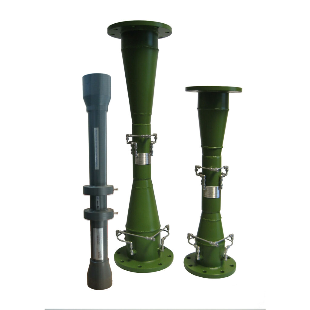
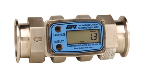
  1. Flowmeters: Flowmeters are devices specifically designed to measure the flow rate of a fluid, including air. There are various types of flowmeters available, such as orifice meters, venturi meters, and magnetic flowmeters. These instruments utilize different principles to measure the flow rate accurately.

  2. Pitot Tubes: Pitot tubes are simple yet effective devices used to measure the velocity of a fluid. They consist of a small tube with one end pointed directly into the fluid flow and the other end connected to a pressure gauge. By measuring the pressure difference between the two ends of the tube, the velocity of the fluid can be determined.

  3. Anemometers: Anemometers are handheld devices commonly used to measure wind speed. However, they can also be used to measure air flow rate in engines. Anemometers typically utilize rotating cups or propellers to determine the velocity of the air, which can then be used to calculate the mass flow rate.

Formula for Air Mass Flow Rate

Once the necessary measurements of volume flow rate, density, and velocity have been obtained, the mass flow rate of air can be calculated using a simple formula. The formula for calculating the mass flow rate is as follows:

Mass Flow Rate = Volume Flow Rate x Density

The volume flow rate represents the amount of air passing through the engine per unit of time, usually measured in cubic meters per second (m³/s). The density of the air is the mass of the air per unit volume, typically measured in kilograms per cubic meter (kg/m³).

By multiplying the volume flow rate by the density, we obtain the mass flow rate of air. This value represents the actual mass of air passing through the engine per unit of time and is crucial for understanding the engine’s performance and efficiency.

It is important to note that the units used in the calculations should be consistent. For example, if the volume flow rate is measured in cubic feet per minute (CFM), it should be converted to cubic meters per second (m³/s) before calculating the mass flow rate.

In conclusion, calculating the mass flow rate of air in an engine is a fundamental aspect of understanding its performance. By accurately measuring the volume flow rate, density, and velocity of the air, and applying the appropriate formula, engineers and researchers can gain valuable insights into the engine’s efficiency and make informed decisions for optimization and improvement.

How to Calculate Mass Flow Rate of Dry Air

To understand how to calculate the mass flow rate of dry air, we need to start by defining what mass flow rate is. Mass flow rate is a fundamental concept in fluid dynamics that measures the amount of mass passing through a given point per unit of time. In the case of dry air, it refers to the amount of air passing through a specific location in a system.

Calculation of Mass Flow Rate of Dry Air

Calculating the mass flow rate of dry air involves considering several factors, such as the volume flow rate, density, and velocity of the air. The formula for calculating mass flow rate is:

Mass Flow Rate = Volume Flow Rate x Density

Let’s break down each component of the formula and understand how to calculate them.

1. Volume Flow Rate

The volume flow rate represents the volume of air passing through a given point per unit of time. It is usually measured in cubic meters per second (m³/s) or cubic feet per minute (CFM). To calculate the volume flow rate, you need to know the cross-sectional area of the flow and the velocity of the air.

The formula for volume flow rate is:

Volume Flow Rate = Cross-sectional Area x Velocity

To find the cross-sectional area, you can measure the dimensions of the pipe, duct, or any other conduit through which the air is flowing. Once you have the cross-sectional area, you need to determine the velocity of the air. This can be done using various methods, such as using a flowmeter or calculating it based on the pressure difference across a nozzle or an orifice.

2. Density

Density is a measure of how much mass is contained in a given volume of a substance. In the case of dry air, density is affected by factors such as temperature, pressure, and humidity. However, for simplicity, we will assume that the air is at a constant temperature and pressure.

The density of dry air can be calculated using the ideal gas law:

Density = (Pressure x Molecular Weight) / (Gas Constant x Temperature)

Where:
– Pressure is the absolute pressure of the air in Pascals (Pa)
Molecular Weight is the molar mass of dry air, which is approximately 28.97 grams per mole (g/mol)
– Gas Constant is the ideal gas constant, which is approximately 8.314 J/(mol·K)
– Temperature is the absolute temperature of the air in Kelvin (K)

3. Calculation

Now that we have the volume flow rate and the density, we can calculate the mass flow rate of dry air by multiplying the two values together:

Mass Flow Rate = Volume Flow Rate x Density

It’s important to note that the units used for each component of the calculation should be consistent. For example, if the volume flow rate is measured in cubic meters per second (m³/s) and the density is in kilograms per cubic meter (kg/m³), the resulting mass flow rate will be in kilograms per second (kg/s).

By calculating the mass flow rate of dry air, we can gain valuable insights into various engineering and thermodynamic applications. Understanding the mass flow rate is crucial for designing efficient HVAC systems, optimizing combustion processes, and analyzing fluid mechanics in a wide range of industries.

In conclusion, calculating the mass flow rate of dry air involves determining the volume flow rate and the density of the air. By using the appropriate formulas and units, engineers and scientists can accurately quantify the amount of air passing through a specific point in a system. This knowledge is essential for designing and optimizing various processes that rely on the flow of dry air.

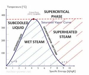
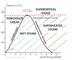
How to Calculate Mass Flow Rate of Steam

To calculate the mass flow rate of steam, we need to understand the basic principles of fluid dynamics and conservation of mass. Mass flow rate is a fundamental concept in engineering, thermodynamics, and fluid mechanics, and it plays a crucial role in various applications such as nozzle design, pipe flow analysis, orifice sizing, and flowmeter calibration.

Formula for Steam Mass Flow Rate

The mass flow rate of steam can be calculated using the equation:

Mass Flow Rate = Volume Flow Rate x Density

The volume flow rate represents the amount of steam passing through a given cross-sectional area per unit time, while the density is the mass per unit volume of the steam. By multiplying these two values, we can determine the mass flow rate of steam.

To calculate the volume flow rate, we can use the equation:

Volume Flow Rate = Velocity x Cross-Sectional Area

The velocity represents the speed at which the steam is flowing, while the cross-sectional area is the area perpendicular to the direction of flow. By multiplying these two values, we can determine the volume flow rate of steam.

Units and Measurements

When calculating the mass flow rate of steam, it is essential to ensure that the units are consistent. The most commonly used unit for mass flow rate is kilograms per second (kg/s). However, other units such as pounds per hour (lb/hr) or grams per minute (g/min) may also be used depending on the specific application.

Similarly, the units for volume flow rate can vary, with cubic meters per second (m³/s) being the standard SI unit. Other units such as cubic feet per minute (cfm) or liters per minute (L/min) are also commonly used.

To obtain accurate results, it is crucial to measure the velocity and cross-sectional area correctly. Various techniques and instruments, such as Pitot tubes, flowmeters, orifice plates, and ultrasonic flowmeters, can be used to measure these parameters accurately.

Example Calculation

Let’s consider an example to illustrate the calculation of the mass flow rate of steam. Suppose we have a steam pipe with a velocity of 10 m/s and a cross-sectional area of 0.5 m². The density of the steam is 2 kg/m³.

First, we calculate the volume flow rate:

Volume Flow Rate = Velocity x Cross-Sectional Area
= 10 m/s x 0.5 m²
= 5 m³/s

Next, we calculate the mass flow rate:

Mass Flow Rate = Volume Flow Rate x Density
= 5 m³/s x 2 kg/m³
= 10 kg/s

Therefore, the mass flow rate of steam in this example is 10 kg/s.

Conclusion

Calculating the mass flow rate of steam is a fundamental concept in fluid dynamics and thermodynamics. By understanding the principles of conservation of mass and using the appropriate equations, we can accurately determine the mass flow rate of steam. It is crucial to ensure consistent units and accurate measurements of velocity and cross-sectional area to obtain reliable results.

How to Calculate Mass Flow Rate of Exhaust Gas
Ref
wikipedia

Importance of Exhaust Gas Mass Flow Rate

When it comes to understanding and optimizing the performance of engines and exhaust systems, calculating the mass flow rate of exhaust gas is of utmost importance. The mass flow rate provides crucial information about the amount of exhaust gas being expelled from the system per unit of time. By accurately determining the mass flow rate, engineers and researchers can evaluate the efficiency of combustion processes, assess emissions, and design effective exhaust systems.

The mass flow rate of exhaust gas is particularly significant in the automotive industry, where it plays a vital role in meeting emission standards and improving fuel efficiency. It helps engineers identify potential issues such as incomplete combustion, excessive emissions, or restricted flow, allowing them to make necessary adjustments to enhance engine performance and reduce environmental impact.

Calculation of Exhaust Gas Mass Flow Rate

To calculate the mass flow rate of exhaust gas, we need to consider several factors, including the volume flow rate, density, and velocity of the gas. The equation used to calculate mass flow rate is:

Mass Flow Rate = Volume Flow Rate x Density

Let’s break down the steps involved in calculating the mass flow rate:

  1. Determine the Volume Flow Rate:
    The volume flow rate represents the amount of gas passing through a given point in the system per unit of time. It is typically measured in cubic meters per second (m³/s) or cubic feet per minute (CFM). To calculate the volume flow rate, you can use various methods such as flowmeters, orifice plates, or differential pressure devices.

  2. Determine the Density:
    The density of the gas is a measure of its mass per unit volume. It is typically expressed in kilograms per cubic meter (kg/m³) or pounds per cubic foot (lb/ft³). The density of exhaust gas depends on factors such as temperature, pressure, and composition. It can be obtained from gas property tables or calculated using equations based on the ideal gas law.

  3. Calculate the Mass Flow Rate:
    Once you have the volume flow rate and density, you can multiply them together to obtain the mass flow rate. The resulting value will be expressed in kilograms per second (kg/s) or pounds per minute (lb/min), depending on the units used for volume flow rate and density.

It is important to note that the mass flow rate remains constant throughout a closed system, in accordance with the principle of conservation of mass. This means that regardless of changes in velocity or cross-sectional area, the mass flow rate will remain the same as long as there are no additions or subtractions of mass within the system.

In engineering and thermodynamics, accurately calculating the mass flow rate of exhaust gas is crucial for designing efficient systems, optimizing performance, and meeting regulatory requirements. By understanding the principles and equations involved, engineers can make informed decisions to improve the overall efficiency and environmental impact of exhaust systems.

How to Calculate Mass Flow Rate of Gas

Calculation of Mass Flow Rate of Gas

When it comes to fluid dynamics, calculating the mass flow rate of a gas is an essential task. Mass flow rate refers to the amount of mass that passes through a given point per unit of time. It is a crucial parameter in various fields, including engineering, thermodynamics, and fluid mechanics. In this section, we will explore how to calculate the mass flow rate of a gas and understand the underlying principles.

To calculate the mass flow rate of a gas, we need to consider a few key factors: the volume flow rate, density, and velocity of the gas. The equation for mass flow rate is derived from the principle of conservation of mass, which states that mass cannot be created or destroyed, only transferred or transformed.

The equation for mass flow rate is as follows:

Mass Flow Rate = Volume Flow Rate x Density

Let’s break down each component of the equation to understand how to calculate the mass flow rate of a gas.

Volume Flow Rate

The volume flow rate refers to the volume of gas that passes through a given point per unit of time. It is typically measured in cubic meters per second (m³/s) or cubic feet per minute (CFM). To calculate the volume flow rate, we need to multiply the cross-sectional area of the flow by the velocity of the gas.

Volume Flow Rate = Cross-Sectional Area x Velocity

Density

Density is a measure of how much mass is contained in a given volume of a substance. In the context of gas flow, density is typically measured in kilograms per cubic meter (kg/m³) or pounds per cubic foot (lb/ft³). The density of a gas depends on various factors, including temperature and pressure. It can be calculated using the ideal gas law or obtained from reference tables.

Velocity

Velocity refers to the speed at which the gas is flowing. It is typically measured in meters per second (m/s) or feet per second (ft/s). The velocity of a gas can be determined using various methods, such as using a flowmeter, measuring the pressure difference across a nozzle or orifice, or using Bernoulli’s equation.

Once we have determined the volume flow rate, density, and velocity of the gas, we can plug these values into the equation for mass flow rate to calculate the desired parameter.

Units and Measurement

When calculating the mass flow rate of a gas, it is crucial to ensure that all the units are consistent. For example, if the volume flow rate is measured in cubic meters per second, the density should be in kilograms per cubic meter, and the resulting mass flow rate will be in kilograms per second. It is essential to convert units if necessary to maintain consistency and accuracy in the calculations.

In engineering and scientific applications, precise measurements are crucial. Therefore, it is essential to use accurate instruments and techniques to measure the various parameters involved in calculating the mass flow rate of a gas. Flowmeters, pressure sensors, and temperature sensors are commonly used tools in these measurements.

Understanding how to calculate the mass flow rate of a gas is fundamental in many engineering and scientific disciplines. By considering the volume flow rate, density, and velocity of the gas, we can determine the amount of mass that passes through a given point per unit of time. This knowledge is invaluable in designing and optimizing systems that involve gas flow, such as pipelines, nozzles, and ventilation systems.

How to Calculate Mass Flow Rate of Refrigerant

Determining Refrigerating Capacity

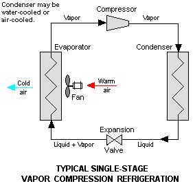
When it comes to refrigeration systems, understanding the mass flow rate of the refrigerant is crucial for efficient operation. The mass flow rate refers to the amount of refrigerant that passes through a specific point in the system per unit of time. By calculating the mass flow rate, engineers and technicians can determine the refrigerating capacity of the system and make informed decisions regarding its performance and efficiency.

To determine the refrigerating capacity, several factors need to be considered. These include the specific heat capacity of the refrigerant, the temperature difference across the evaporator or condenser, and the rate at which heat is transferred. By analyzing these factors, it becomes possible to calculate the mass flow rate of the refrigerant accurately.

Calculation of Mass Flow Rate of Refrigerant

To calculate the mass flow rate of the refrigerant, engineers and technicians rely on a combination of fluid dynamics principles and thermodynamic equations. The mass flow rate can be determined using the equation:

Mass Flow Rate = Volume Flow Rate x Density

The volume flow rate refers to the volume of refrigerant passing through a given point in the system per unit of time. It can be calculated using the equation:

Volume Flow Rate = Velocity x Cross-sectional Area

The velocity represents the speed at which the refrigerant is flowing, while the cross-sectional area refers to the area through which the refrigerant is passing. By multiplying these two values, the volume flow rate can be obtained.

The density of the refrigerant is a crucial parameter in the calculation. It represents the mass per unit volume of the refrigerant and can vary depending on factors such as temperature and pressure. To determine the density, engineers and technicians often rely on tables or equations specific to the refrigerant being used.

Once the volume flow rate and density are known, the mass flow rate can be calculated by multiplying these two values together. The resulting value represents the amount of refrigerant passing through the system per unit of time and is typically measured in kilograms per second (kg/s) or pounds per second (lb/s).

It is important to note that the mass flow rate is subject to the principle of conservation of mass. This principle states that mass cannot be created or destroyed but can only be transferred or transformed. Therefore, the mass flow rate entering a specific point in the system must be equal to the mass flow rate exiting that point.

In practical applications, engineers and technicians often use various measurement devices such as flowmeters, nozzles, orifices, or pressure sensors to determine the relevant parameters required for calculating the mass flow rate. These devices provide accurate readings and allow for precise calculations, ensuring the efficient operation of refrigeration systems.

In conclusion, calculating the mass flow rate of refrigerant is essential for understanding the performance and efficiency of refrigeration systems. By considering factors such as the specific heat capacity, temperature difference, and heat transfer rate, engineers and technicians can accurately determine the refrigerating capacity. Using fluid dynamics principles and thermodynamic equations, the mass flow rate can be calculated by multiplying the volume flow rate and density of the refrigerant. This information enables informed decision-making and optimization of refrigeration systems for maximum efficiency.

How to Calculate Mass Flow Rate of Dry Air

To calculate the mass flow rate of dry air, we need to understand the basic principles of fluid dynamics and the equation that governs mass flow rate. Mass flow rate is a fundamental concept in engineering, thermodynamics, and fluid mechanics, and it is crucial for various applications such as designing pipes, nozzles, orifices, and flowmeters.

Calculation of Mass Flow Rate of Dry Air

The mass flow rate of a fluid is defined as the amount of mass passing through a given cross-sectional area per unit time. In the case of dry air, we can calculate the mass flow rate using the equation:

Mass Flow Rate (ṁ) = Density (ρ) x Volume Flow Rate (Q)

The density of dry air can be approximated using the ideal gas law, which states that the density is directly proportional to the pressure and inversely proportional to the temperature. However, for simplicity, we will assume constant density in this calculation.

To calculate the volume flow rate of dry air, we need to know the velocity and the cross-sectional area through which the air is flowing. The volume flow rate (Q) is given by the equation:

Volume Flow Rate (Q) = Velocity (V) x Cross-Sectional Area (A)

Now, let’s break down the steps to calculate the mass flow rate of dry air:

  1. Measure the velocity (V) of the air: To determine the velocity, you can use various methods such as an anemometer or a pitot tube. Ensure that the velocity measurement is taken at the same location and under the same conditions as the cross-sectional area measurement.

  2. Measure the cross-sectional area (A) through which the air is flowing: This can be done by directly measuring the dimensions of the pipe, nozzle, or orifice through which the air is passing. Alternatively, you can use a flowmeter that provides the cross-sectional area measurement.

  3. Calculate the volume flow rate (Q): Multiply the velocity (V) by the cross-sectional area (A) to obtain the volume flow rate (Q).

  4. Determine the density (ρ) of dry air: As mentioned earlier, the density of dry air can be approximated using the ideal gas law. However, for simplicity, we will assume a constant density value.

  5. Calculate the mass flow rate (ṁ): Multiply the density (ρ) by the volume flow rate (Q) to obtain the mass flow rate (ṁ) of dry air.

To summarize, the mass flow rate of dry air can be calculated by multiplying the density of dry air by the volume flow rate of the air. The volume flow rate is obtained by multiplying the velocity of the air by the cross-sectional area through which it is flowing. By following these steps and using the appropriate units of measurement, you can accurately determine the mass flow rate of dry air for your specific application.

Steps Calculation
1. Measure the velocity (V) of the air Use an anemometer or pitot tube
2. Measure the cross-sectional area (A) Direct measurement or flowmeter
3. Calculate the volume flow rate (Q) Multiply velocity (V) by cross-sectional area (A)
4. Determine the density (ρ) of dry air Use ideal gas law or assume constant density
5. Calculate the mass flow rate (ṁ) Multiply density (ρ) by volume flow rate (Q)

Remember, understanding and calculating the mass flow rate of dry air is essential for various engineering and scientific applications. By following these steps and utilizing the appropriate measurements and equations, you can accurately determine the mass flow rate and ensure the efficiency and effectiveness of your system.

How to Calculate Mass Flow Rate of Steam

To accurately determine the mass flow rate of steam, we need to understand the underlying principles of fluid dynamics and utilize the appropriate equations. Mass flow rate is a crucial parameter in various engineering applications, including thermodynamics, fluid mechanics, and measurement.

Formula for Steam Mass Flow Rate

The mass flow rate of steam can be calculated using the equation:

Mass Flow Rate = Volume Flow Rate × Density

The volume flow rate represents the amount of steam passing through a given point per unit time, while density refers to the mass per unit volume of the steam. By multiplying these two values together, we can obtain the mass flow rate of the steam.

To calculate the volume flow rate, we can use the equation:

Volume Flow Rate = Velocity × Cross-Sectional Area

The velocity represents the speed at which the steam is flowing, while the cross-sectional area refers to the area perpendicular to the direction of flow. By multiplying these two values, we can determine the volume flow rate.

Conservation of Mass

The concept of conservation of mass is fundamental in fluid dynamics. According to this principle, the mass entering a system must equal the mass leaving the system. This principle allows us to calculate the mass flow rate by measuring the volume flow rate and density at a specific point.

Units and Measurement

When calculating the mass flow rate of steam, it is essential to ensure that the units are consistent. The SI unit for mass flow rate is kilograms per second (kg/s), while the unit for volume flow rate is cubic meters per second (m³/s). Density is typically measured in kilograms per cubic meter (kg/m³), and velocity is measured in meters per second (m/s).

To obtain accurate measurements, engineers often use specialized instruments such as flowmeters, nozzles, orifices, and pressure sensors. These devices allow for precise measurement of parameters required to calculate the mass flow rate.

Example Calculation

Let’s consider an example to illustrate the calculation of the mass flow rate of steam. Suppose we have a steam pipe with a velocity of 10 m/s and a cross-sectional area of 0.5 m². The density of the steam is 2 kg/m³.

First, we calculate the volume flow rate:

Volume Flow Rate = Velocity × Cross-Sectional Area
Volume Flow Rate = 10 m/s × 0.5 m²
Volume Flow Rate = 5 m³/s

Next, we calculate the mass flow rate:

Mass Flow Rate = Volume Flow Rate × Density
Mass Flow Rate = 5 m³/s × 2 kg/m³
Mass Flow Rate = 10 kg/s

Therefore, the mass flow rate of steam in this example is 10 kg/s.

In conclusion, calculating the mass flow rate of steam involves understanding the principles of fluid dynamics, utilizing appropriate equations, and ensuring consistent units and measurements. By following these steps, engineers can accurately determine the mass flow rate, a crucial parameter in various engineering applications.

How to Calculate Mass Flow Rate of Water

To understand how to calculate the mass flow rate of water, we first need to grasp the concept of mass flow rate itself. Mass flow rate is a fundamental parameter in fluid dynamics that measures the amount of mass passing through a given point per unit of time. It is an essential quantity in various fields, including engineering, thermodynamics, and fluid mechanics.

Calculation of Mass Flow Rate of Water

The mass flow rate of water can be calculated using a simple equation derived from the principle of conservation of mass. The equation is as follows:

Mass Flow Rate = Density × Volume Flow Rate

To calculate the mass flow rate, we need to determine the density of the water and the volume flow rate.

Determining the Density of Water

The density of water is a well-known value and can be considered constant under normal conditions. At room temperature and atmospheric pressure, the density of water is approximately 1000 kilograms per cubic meter (kg/m³). However, it is important to note that the density of water can vary slightly with temperature and pressure. For most practical purposes, using the average density of 1000 kg/m³ is sufficient.

Measuring the Volume Flow Rate

To calculate the mass flow rate, we also need to determine the volume flow rate of water. The volume flow rate measures the amount of water passing through a given point per unit of time. It is typically expressed in cubic meters per second (m³/s) or liters per second (L/s).

There are various methods to measure the volume flow rate of water, depending on the application and available equipment. Some common techniques include using a flowmeter, a nozzle, an orifice, or a pipe with known dimensions. These devices can provide accurate measurements of the volume flow rate.

Once we have determined the volume flow rate, we can proceed with calculating the mass flow rate of water.

Calculating the Mass Flow Rate

To calculate the mass flow rate, we multiply the density of water by the volume flow rate. Let’s consider an example to illustrate this calculation:

Suppose we have a volume flow rate of 0.5 cubic meters per second (m³/s) of water. Using the average density of water (1000 kg/m³), we can calculate the mass flow rate as follows:

Mass Flow Rate = Density × Volume Flow Rate
= 1000 kg/m³ × 0.5 m³/s
= 500 kg/s

Therefore, the mass flow rate of water in this example is 500 kilograms per second (kg/s).

It is important to note that the units used for the density and volume flow rate must be consistent to obtain accurate results. Additionally, when working with different units, appropriate conversions should be applied to ensure accurate calculations.

In conclusion, calculating the mass flow rate of water involves determining the density of water and the volume flow rate. By multiplying these two values together, we can obtain the mass flow rate. This calculation is crucial in various applications, such as fluid dynamics, engineering, and thermodynamics, where understanding the movement of fluids is essential.

How to Calculate Mass Flow Rate from Enthalpy

In fluid dynamics, calculating the mass flow rate is an essential task that helps engineers and scientists understand the movement of fluids through a system. One way to determine the mass flow rate is by utilizing the concept of enthalpy. Enthalpy is a thermodynamic property that accounts for the internal energy of a fluid, including its heat content and work done. By considering the change in enthalpy across a system, we can calculate the mass flow rate accurately.

Calculation of Mass Flow Rate from Enthalpy

To calculate the mass flow rate from enthalpy, we need to consider the conservation of mass principle. According to this principle, the mass entering a system must equal the mass leaving the system. By applying this principle and utilizing the equation for enthalpy, we can determine the mass flow rate.

The equation for mass flow rate from enthalpy is as follows:

Mass Flow Rate (ṁ) = (Enthalpy Change (ΔH)) / (Specific Enthalpy (h))

Where:
– Mass Flow Rate
(ṁ) is the amount of mass passing through a given point per unit time.
– Enthalpy Change (ΔH) is the difference in enthalpy between the inlet and outlet of the system.
– Specific Enthalpy (h) is the enthalpy per unit mass of the fluid.

By rearranging the equation, we can solve for the mass flow rate:

ṁ = ΔH / h

To calculate the mass flow rate, we need to know the enthalpy change and the specific enthalpy of the fluid. The enthalpy change can be determined by measuring the heat transfer or work done on the fluid. The specific enthalpy can be obtained from tables or equations specific to the fluid being analyzed.

It is important to note that the units of the enthalpy change and specific enthalpy must be consistent for accurate calculations. Common units for enthalpy include joules (J) or kilojoules (kJ), while specific enthalpy is typically measured in joules per kilogram (J/kg) or kilojoules per kilogram (kJ/kg).

Example Calculation

Let’s consider an example to illustrate the calculation of mass flow rate from enthalpy. Suppose we have a system where the enthalpy change is 500 kJ and the specific enthalpy is 50 kJ/kg. We can use the equation mentioned earlier to find the mass flow rate:

ṁ = ΔH / h

ṁ = 500 kJ / 50 kJ/kg

ṁ = 10 kg/s

In this example, the mass flow rate is determined to be 10 kilograms per second.

Conclusion

Calculating the mass flow rate from enthalpy is a fundamental concept in fluid dynamics. By considering the conservation of mass principle and utilizing the equation for enthalpy, engineers and scientists can accurately determine the amount of mass passing through a system per unit time. This calculation is crucial for various applications in engineering and thermodynamics, allowing for a better understanding of fluid mechanics and system performance.

How to Calculate Mass Flow Rate from Pressure Drop

In fluid dynamics, calculating the mass flow rate is an essential task in various engineering applications. One common method to determine the mass flow rate is by measuring the pressure drop across a system. By understanding the relationship between pressure drop and mass flow rate, we can gain valuable insights into the behavior of fluids in different scenarios.

Calculation of Mass Flow Rate from Pressure Drop

To calculate the mass flow rate from a pressure drop, we need to consider several factors, including the fluid’s density, velocity, and the cross-sectional area of the flow. The equation we use to calculate the mass flow rate is derived from the principle of conservation of mass.

The equation for mass flow rate is as follows:

Mass Flow Rate = Density * Velocity * Cross-sectional Area

Let’s break down each component of the equation to understand how they contribute to the calculation.

Density

Density is a measure of how much mass is contained within a given volume of a substance. It is usually represented by the Greek letter rho (ρ) and is measured in kilograms per cubic meter (kg/m³). The density of a fluid is influenced by factors such as temperature and pressure.

To calculate the mass flow rate, we need to know the density of the fluid. This information can be obtained from fluid property tables or by using equations specific to the fluid being analyzed.

Velocity

Velocity refers to the speed at which the fluid is flowing through a particular point in the system. It is typically measured in meters per second (m/s). The velocity of the fluid can be determined by measuring the flow rate or by using flow measurement devices such as flowmeters.

Cross-sectional Area

The cross-sectional area is the area perpendicular to the direction of flow. It represents the size of the opening through which the fluid is passing. The cross-sectional area is measured in square meters (m²) and can be calculated using the dimensions of the flow path, such as the diameter of a pipe or the dimensions of a nozzle or orifice.

Putting It All Together

To calculate the mass flow rate from a pressure drop, we need to gather the necessary information: the density of the fluid, the velocity of the flow, and the cross-sectional area of the system. Once we have these values, we can plug them into the equation mentioned earlier:

Mass Flow Rate = Density * Velocity * Cross-sectional Area

By substituting the appropriate units for each variable, we can obtain the mass flow rate in units such as kilograms per second (kg/s) or pounds per hour (lb/hr), depending on the desired measurement.

Example Calculation

Let’s consider an example to illustrate the calculation of mass flow rate from a pressure drop. Suppose we have a pipe with a diameter of 0.5 meters and a fluid flowing through it with a velocity of 2 meters per second. The density of the fluid is 1000 kilograms per cubic meter.

Using the equation mentioned earlier, we can calculate the cross-sectional area of the pipe:

Cross-sectional Area = π * (Diameter/2)^2
= π * (0.5/2)^2
= 0.1963 square meters

Now, we can calculate the mass flow rate:

Mass Flow Rate = Density * Velocity * Cross-sectional Area
= 1000 kg/m³ * 2 m/s * 0.1963 m²
= 392.6 kg/s

Therefore, the mass flow rate through the pipe is 392.6 kilograms per second.

Conclusion

Calculating the mass flow rate from a pressure drop is a fundamental concept in fluid mechanics and engineering. By understanding the relationship between pressure drop, density, velocity, and cross-sectional area, we can accurately determine the mass flow rate of a fluid. This knowledge is crucial in various industries, including manufacturing, energy, and transportation, where the efficient movement of fluids is essential for optimal system performance.

How to Calculate Mass Flow Rate of Fuel in an Engine

Fuel mass flow rate is an important parameter to consider when analyzing the performance of an engine. It helps us understand how much fuel is being consumed and how efficiently it is being utilized. By calculating the mass flow rate of fuel, we can gain insights into the engine’s efficiency and make informed decisions regarding its operation and optimization.

Calculation of Fuel Mass Flow Rate in an Engine

To calculate the mass flow rate of fuel in an engine, we need to consider several factors, including the volume flow rate, density, and velocity of the fuel. The equation used to calculate the mass flow rate is derived from the principle of conservation of mass.

  1. Determine the Volume Flow Rate: The volume flow rate represents the amount of fuel passing through a specific point in the engine per unit time. It is typically measured in liters per second (L/s) or cubic meters per second (m³/s). To calculate the volume flow rate, we need to know the cross-sectional area of the flow path and the velocity of the fuel.

  2. Measure the Cross-Sectional Area: The cross-sectional area refers to the area perpendicular to the direction of flow. It can be determined by measuring the dimensions of the flow path, such as the diameter of a pipe or the area of an orifice. Ensure that the units of the cross-sectional area are consistent with the units used for the velocity and density.

  3. Determine the Velocity of the Fuel: The velocity of the fuel represents the speed at which it flows through the engine. It can be measured using various techniques, such as flowmeters or by calculating it based on the pressure drop across a nozzle. Ensure that the units of velocity are consistent with the units used for the cross-sectional area and density.

  4. Calculate the Density of the Fuel: The density of the fuel is a measure of its mass per unit volume. It can vary depending on the type of fuel being used. The density is typically provided by fuel manufacturers and can be expressed in kilograms per cubic meter (kg/m³) or grams per cubic centimeter (g/cm³).

  5. Apply the Mass Flow Rate Equation: Once we have obtained the volume flow rate, density, and velocity of the fuel, we can calculate the mass flow rate using the equation:

Mass Flow Rate = Volume Flow Rate × Density

Ensure that the units of the mass flow rate are consistent with the units used for the volume flow rate and density. It is also important to note that the mass flow rate can be positive or negative, depending on the direction of flow.

By following these steps and accurately measuring the necessary parameters, we can calculate the mass flow rate of fuel in an engine. This information can be used to monitor fuel consumption, optimize engine performance, and make informed decisions regarding fuel efficiency. Understanding the mass flow rate is crucial for engineers and technicians working in the field of thermodynamics, fluid mechanics, and engineering.

How to Calculate Mass Flow Rate in Ansys Fluent

Introduction to Ansys Fluent

Ansys Fluent is a powerful computational fluid dynamics (CFD) software widely used in engineering and scientific applications. It allows engineers and researchers to simulate and analyze fluid flow, heat transfer, and other related phenomena. One important parameter in fluid dynamics is the mass flow rate, which measures the amount of mass passing through a given point per unit time. Calculating the mass flow rate accurately is crucial for understanding and optimizing various processes involving fluids.

Calculation of Mass Flow Rate in Ansys Fluent

To calculate the mass flow rate in Ansys Fluent, we need to consider the fundamental principle of conservation of mass. According to this principle, the mass entering a control volume must be equal to the mass leaving it, assuming no mass is being generated or consumed within the volume.

To calculate the mass flow rate, we can use the equation:

Mass Flow Rate = Density × Velocity × Cross-sectional Area

Let’s break down each component of this equation:

  1. Density: Density is a measure of how much mass is contained within a given volume of a substance. It is typically denoted by the symbol ρ and is expressed in units such as kg/m³ or g/cm³. In Ansys Fluent, the density of the fluid can be specified based on the properties of the material being simulated.

  2. Velocity: Velocity refers to the speed at which the fluid is flowing. It is denoted by the symbol v and is typically measured in units of meters per second (m/s) or feet per second (ft/s). In Ansys Fluent, the velocity can be obtained from the simulation results or specified as an input parameter.

  3. Cross-sectional Area: The cross-sectional area represents the area perpendicular to the flow direction. It is denoted by the symbol A and is typically measured in square meters (m²) or square feet (ft²). The cross-sectional area depends on the geometry of the system under consideration, such as the shape of a pipe, nozzle, orifice, or flowmeter.

By multiplying the density, velocity, and cross-sectional area, we can determine the mass flow rate. It is important to ensure that the units of each component are consistent to obtain accurate results.

Example Calculation

Let’s consider a simple example to illustrate the calculation of mass flow rate in Ansys Fluent. Suppose we have a pipe with a diameter of 0.1 meters and water flowing through it at a velocity of 2 meters per second. The density of water is approximately 1000 kg/m³.

To calculate the mass flow rate, we first need to determine the cross-sectional area of the pipe. The cross-sectional area of a pipe can be calculated using the formula:

Cross-sectional Area = π × (Diameter/2)²

Substituting the values into the equation:

Cross-sectional Area = π × (0.1/2)² = 0.00785 m²

Next, we multiply the density, velocity, and cross-sectional area:

Mass Flow Rate = 1000 kg/m³ × 2 m/s × 0.00785 m² = 15.7 kg/s

Therefore, the mass flow rate of water through the pipe is 15.7 kilograms per second.

Conclusion

Calculating the mass flow rate in Ansys Fluent is essential for understanding and analyzing fluid dynamics in various engineering and scientific applications. By considering the principles of conservation of mass and using the equation involving density, velocity, and cross-sectional area, engineers and researchers can accurately determine the mass flow rate. This information is crucial for designing and optimizing systems involving fluid flow, such as pipes, nozzles, orifices, and flowmeters.

Frequently Asked Questions

How to calculate mass flow rate in a heat exchanger?

To calculate the mass flow rate in a heat exchanger, you can use the equation:

[ text{Mass Flow Rate} = text{Volume Flow Rate} times text{Density} ]

How to calculate mass flow rate in Paraview?

Paraview is a visualization software and does not directly calculate mass flow rate. However, you can export the data from Paraview and use other tools or equations to calculate the mass flow rate.

How to calculate mass flow rate of a compressor?

To calculate the mass flow rate of a compressor, you can use the equation:

[ text{Mass Flow Rate} = text{Volume Flow Rate} times text{Density} ]

How to find mass flow rate in thermodynamics?

In thermodynamics, you can find the mass flow rate by using the equation:

[ text{Mass Flow Rate} = text{Volume Flow Rate} times text{Density} ]

How to calculate mass flow rate of exhaust gas?

To calculate the mass flow rate of exhaust gas, you can use the equation:

[ text{Mass Flow Rate} = text{Volume Flow Rate} times text{Density} ]

How to calculate mass flow rate of gas?

To calculate the mass flow rate of a gas, you can use the equation:

[ text{Mass Flow Rate} = text{Volume Flow Rate} times text{Density} ]

How to calculate mass flow rate from density?

To calculate the mass flow rate from density, you can use the equation:

[ text{Mass Flow Rate} = text{Volume Flow Rate} times text{Density} ]

How to calculate mass flow rate of air?

To calculate the mass flow rate of air, you can use the equation:

[ text{Mass Flow Rate} = text{Volume Flow Rate} times text{Density} ]

How to calculate mass flow rate of refrigerant?

To calculate the mass flow rate of a refrigerant, you can use the equation:

[ text{Mass Flow Rate} = text{Volume Flow Rate} times text{Density} ]

How to calculate mass flow rate of dry air?

wikipedia

To calculate the mass flow rate of dry air, you can use the equation:

[ text{Mass Flow Rate} = text{Volume Flow Rate} times text{Density} ]

How to calculate mass flow rate of steam?

gif
wikipedia

To calculate the mass flow rate of steam, you can use the equation:

[ text{Mass Flow Rate} = text{Volume Flow Rate} times text{Density} ]

How to calculate mass flow rate of water?

To calculate the mass flow rate of water, you can use the equation:

[ text{Mass Flow Rate} = text{Volume Flow Rate} times text{Density} ]

How to calculate mass flow rate from enthalpy?

To calculate the mass flow rate from enthalpy, you can use the equation:

[ text{Mass Flow Rate} = frac{text{Heat Transfer Rate}}{text{Enthalpy Difference}} ]

How to calculate mass flow rate from pressure drop?

To calculate the mass flow rate from pressure drop, you can use the equation:

[ text{Mass Flow Rate} = frac{text{Pressure Drop}}{text{Resistance}} ]

How to calculate mass flow rate of fuel in an engine?

gif
wikipedia

To calculate the mass flow rate of fuel in an engine, you can use the equation:

[ text{Mass Flow Rate} = text{Fuel Flow Rate} times text{Density} ]

How to calculate mass flow rate?

To calculate the mass flow rate, you can use the equation:

[ text{Mass Flow Rate} = text{Volume Flow Rate} times text{Density} ]

How to calculate mass flow rate in ANSYS Fluent?

In ANSYS Fluent, you can calculate the mass flow rate by post-processing the simulation results. The software provides tools to extract the mass flow rate from the simulation domain.

Volumetric Flow Rate To Velocity: How To Find

dia9 300x84 1

The relationship of Volumetric Flow Rate to Velocity should be calculated properly for the pipeline design of an industry.

Volumetric Flow Rate is the volume of a fluid flows through a tube, duct, channel or other this type of structure per unit time. Velocity refers how fast a fluid is moving through a particular passage per unit time.

Volume Flow Rate, Q or V=Av

Where A= Cross sectional area of a section in m2

And      v=Average velocity of the fluid through out the section in m/s


The unit of Volume Flow Rate is m3/s(cubic meters/second), m3/h(cubic meter/hour), l/s (litre/second), l/min.(litre/minute),ml/s(millilitre/second) etc.

Suitable unit is decided as per the magnitude of Volumetric Flow Rate. In case of very small flow rate(for example fluid inside a syringe), ml/s is preferred and for very large volume flow rate(for example flow of water in a river), it is expressed in m3/h.

Flow Velocity, v =s/t  

Velocity is denoted by small v

Where  s= Distance covered by the fluid molecules

And  t=Time period

The unit of Velocity is m/s (meter/second), km/h(kilometre/hour) etc.

Is Volume Flow Rate the same as Velocity?

Volume Flow Rate and Velocity are related to each other but if we consider as physical quantities, both of them are quite different from each other.

In simple words Velocity of a fluid refers to how fast the fluid (gas or liquid)moves through a passage in a particular time period. Volume Flow Rate gives us the quantity or volume of a fluid (gas or liquid) flows through a passage within a time period.

Velocity of a fluid is a vector quantity whereas Volume Flow Rate is a scalar quantity since it is a time derivative of volume.

Difference between Volumetric Flow Rate To Velocity

The difference between Volumetric Flow Rate and Velocity as follows:

Volumetric Flow RateVelocity
Volume Flow Rate(Q) is the amount of volume(V) of a fluid flows through a cross sectional area (A) per unit time (t).Velocity of a fluid is defined as the distance(d) travelled by a fluid within a time period( t).
Mathematically, Q = V/tMathematically,
Units: m3/s( SI unit), cm3/s (CGS unit)Units: m/s(SI unit), cm/s(CGS unit)

Relationship of Volumetric Flow Rate To Velocity

If we observe the flow rate of a stream or river, if the velocity of water is high, the Volume Flow Rate of the river is also high.

The following equation gives us the relationship between Volume Flow Rate(Q) and Velocity(v).

Q=A. v

Here A is the cross sectional area and v is the velocity of the fluid.

Generally we consider here the average velocity since the velocity of flow does not remain constant throughout the particular time period. Hence,  

  Eq(1)

From Eq (1), it is clear that Volume Flow Rate is directly proportional to both average velocity of the flow and the size of the passage( may be pipe, duct or a river).

The larger the diameter of the pipe or duct, greater is the cross sectional area

dia 8
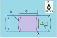
Flow through a pipe with cross sectional area A

In the above figure we can see a pipe with cross sectional area A in m2 and velocity or speed of the fluid is (small v bar)in m/s.

To find out the flow rate or discharge in a process application, two measurements are required: the volume of fluid that crosses the passage and time required by this volume to cross the passage.

Volume Flow Rate,Q= Volume/time

Volume(Capital V) in cubic meter m3 and time(t) in second.

Q=V/t        Eq(2)

In the above figure the volume(V) of fluid that passes through the point(O) within a time period t is represented by the shaded portion of the cinduit is given by

Volume,V=A.d

From Eq(2) Q= V/t = A.d/t

Q = A.d/t   Eq(3)

Now average velocity,

gif

Thus the Eq(3) becomes  

 Volume Flow Rate,

dia 7 1
Flow through a pipe with different cross section

In case of an incompressible fluid(like water) flows through a passage with different cross sectional area, the Volumetric Flow Rate of the fluid  remains constant. To maintain the constant flow rate, the speed of flow is low at a larger  cross sectional area of the pipe and speed becomes high at a smaller cross sectional area.

In the above figure we can see an incompressible liquid flows through a pipe of decreasing cross sectional area. Since the fluid is incompressible in nature it tries to maintain continuity and same volume of fluid flows through each point of the pipe irrespective of the size or diameter of the pipe.

When the size of the pipe is wider at point 1, the velocity of the flow will decrease in comparison to the velocity at point 2 where the pipe becomes narrow. In this way the Flow Rate at each point of the pipe is maintained at a constant value.

At point 1 and 2,

Q1 = Q2

Or,

This is the famous Continuity Equation applicable for Incompressible fluids.

How to find Velocity from Volumetric Flow Rate?

In case of columns of different sizes, it is more convenient to represent flow of a fluid in terms of flow velocity (cm/h). But generally flow is calculated in terms of volume flow rate(ml/min).

Using the following formula we can easily calculate the Velocity of a flow from Volume Flow Rate of a fluid:

Flow Rate,

Where Q= Volume Flow Rate in m3/s

A =Cross sectional area of the passage through which fluid is flowing in m2

Now, bar v=Q/A=Volume Flow Rate/Cross sectional area of the pipe

Flow Rate can also be defined as the ration between the change in volume of the fluid and change in time.

Q=dV/dt

How To Calculate Maximum Principal Stress:With Problems,Tips

To calculate Maximum Principal Stress is one of the basic step for the perfect designing of an engineering structure.

Generally, it had been a common approach to apply maximum principal stress to design a structure and calculating the break down or fracture caused by stress analysis method.

How to Calculate Maximum Principal Stresses?

The Maximum Principal Stress theory gives the idea of the root causes of failure in brittle materials. Depending upon this theory designer can decide the amount of loads which may be withstand by a structure.

Calculation of Maximum Principal Stress:

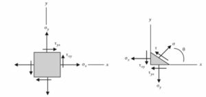
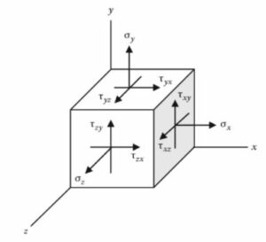
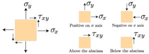
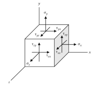
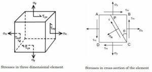
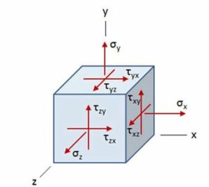
The normal and shear stresses act on a body in 3D is shown in the above figure.

σx,σy,σz are normal stresses .

τxy, τyx, τyz, τzy, τxz, τzx are shear stresses.

When the 3D element is in equilibrium, shear components become

τxy = τyx, τyz = τzy, τxz = τzx Eq(1)

Capture 6
2 D state of stress for an inclined angle; Image Credit: google.co.

In the above figure the stresses act on a stress element at an inclined angle θ can be calculated as follows:

σ = (σx+σy)/2 + (σx- σy)/2cos2θ + τxysin2θ Eq2

τ = – (σx- σy)/2sin2θ + τxycos2θ Eq3

Where the inclination angle θ is defined as

tan2θ = 2τxy/(σx- σy)

Or 2θ = tan-1 (2τxy/(σx- σy)) Eq4

To calculate the Maximum Principal Stresses eq 2 and eq 3 are differentiated wrt θ and set to zero to determine principal angle 2θ. Then Principal angles are substituted back into eq 2 and eq 3 to determine the principal stresses.

dσ/δθ = -(σx- σy) sin 2θ + 2τxycos2θ = 0

tan2θp = 2τxy/(σx- σy) or 2θp = tan-12τxy/(σx- σy) Eq6

Substituting Eq(6) back into Eq (2) and Principal Stresses are shown below:

gif

Eq7

Now for maximum shear

dτ/δθ = -2(σx- σy/2) cos 2θ – 2τxysin2θ = 0

tan2θs = – (σx- σy/ 2τxy)

s = tan -1 – (σx- σy/ 2τxy) Eq9

Substituting eq (9) back into eq(3) and maximum shear stresses are

Eq10

Facts about Maximum Principal Stresses


According to Rankin failure or fracture of a component starts when the maximum value of principal stress exceeds the ultimate stress in a simple tension test.

The Maximum Principal Stress theory is one of the failure theories which mainly explain the causes of failure in case of a brittle material subjected with external loads.
Breakage or crack of a brittle material is always observed at a point where the highest value of Principal stress is equivalent to the ultimate strength. In other words we can say rapture starts at the extremely stressed point of the material.

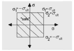
Image 2
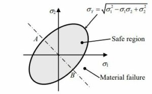
Failure Surface; Image credit: drvsr.files.wordpress.

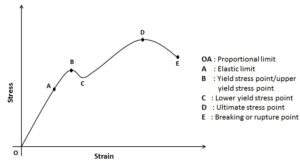
If we consider a component which is acted upon by an external load, we get the stress strain curve as follows:

Image 1
 Stress- strain curve; Image credit: hkdivedi.com

In the above stress strain curve, the highest value of stress(ultimate stress) is observed at point D and at point E fracture of the material starts. Up to point E the material only undergoes plastic and elastic deformation.

We can say as soon as the maximum value of principal stress of the material crosses the point D, failure occurs.

During designing one should always keep in mind that to overcome the situation of failure of a material, maximum principal stress value should be always below the ultimate stress (or yield stress)

Condition for failure of a material

Maximum value of principal stress>Ultimate stress

σ1 > σy or σul

The condition for safe designing of a component is the permissible stress or allowable stress should be greater than the maximum value of the principal stress acting on the body.

The ratio between the yield or ultimate stress and factor of safety is known as Permissible stress of a structure.

Permissible stress = σy or σul / F.O.S

The maximum principal stress failure predictor (MPSFP) design rule (Samuel and Weir, 1999) states that if a body made of brittle material undergoes a stress system where stresses are acted from multiple directions, damage will occur when maximum principal stress of the body is more than the local strength.

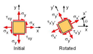
If we change the orientation of the stress element with any of the angle, we will get the stresses for that particular stress state. Now we will try to rotate the element with an angle which will give us the extreme values of the normal stresses.

Capture1
Rotating Stresses from x-y Coordinate
System to new x’-y’ Coordinate System

 Image Credit: ecourses.ou.edu

Here σn = (σx+σy)/2 + (σx- σy)/2cos2θ + τxysin2θ

δσx1/δσ = -(σx- σy) sin2θ + 2τxycos2θ

tan2θp = 2τxy/(σx- σy)

Substituting the value of θp ino the equation we can evaluate the extreme values of stresses. These stresses can be defined as σ1 (maximum) and σ2 (minimum).

image4
Principal Stresses, σ1 and σ2,
at Principal Angle, θp; Image Credit: ecourses.ou.edu

Major Principal Stress,

Minor Principal Stress,

In general, the Principal Stresses σ1 and σ2 can be written as

 ± sign is the only difference of the stress equation which gives major and minor principal stresses.

Certain important points to be noted in Maximum Principal Stress Theory are:

Other name of Maximum Principal Stress theory is Rankine’s theory.

This theory is preferable for safe designing of brittle materials as brittle materials are weak w.r.t tension.

In case of a ductile material structure, Maximum Principal Stress theory is not preferred due to the possibility of shear failure in ductile material is high.


Under certain conditions this theory can also be applied for safe designing of ductile materials which are listed below:

1. Uni axial state of stress

2. Biaxial state of stress in case of like principal stresses

3. Under hydrostatic stress

How To Calculate Principal Stress: Problems, Examples, Facts

dia6 1

Calculating principal stress is an essential aspect of understanding the behavior of materials under different loading conditions. Principal stress refers to the maximum and minimum stress values experienced by a material at a specific point. It plays a crucial role in determining the failure criteria and designing structures to withstand various forces. By calculating the principal stress, engineers and scientists can evaluate the safety and stability of structures, predict material failure, and make informed decisions regarding material selection and design modifications. In this article, we will explore the concept of principal stress and discuss different methods to calculate it, including the graphical method, the Mohr’s circle method, and the mathematical formulae. So, let’s dive in and unravel the mysteries of principal stress calculation.

Key Takeaways

  • Principal stresses can be calculated using the formulas for normal and shear stresses.
  • The principal stresses represent the maximum and minimum stresses experienced at a point in a material.
  • The principal stresses can be used to determine the safety and failure of a material or structure.
  • The principal stress calculation is important in various engineering applications, such as structural analysis and design.

Stress is a fundamental concept in materials science and engineering. It plays a crucial role in determining the behavior and strength of various materials under different conditions. In this section, we will explore the definition and importance of stress in materials, the different types of stress, and the role of stress in three-dimensional objects.

Definition and Importance of Stress in Materials

Stress, in the context of materials science, refers to the internal forces that act on a material. These forces can cause deformation or change in shape, size, or volume. Stress is an essential parameter to consider when designing and analyzing structures, as it helps engineers understand how materials will behave under different loads and conditions.

The importance of stress lies in its ability to influence the mechanical properties of materials. By studying stress, engineers can determine the maximum load a material can withstand before failure, predict the deformation or strain that will occur, and ensure the safety and reliability of structures. Understanding stress is crucial in fields such as mechanical engineering, material science, and structural analysis.

Different Types of Stress: Principal and Shear Stress

There are different types of stress that act on materials, but two primary types are principal stress and shear stress. Let’s take a closer look at each:

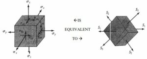
  1. Principal Stress: Principal stress refers to the maximum and minimum stress values that act on a material in different directions. These stresses are perpendicular to each other and occur along specific planes. The maximum principal stress represents the highest tensile or compressive stress, while the minimum principal stress represents the lowest stress. Calculating principal stress is essential for understanding the behavior of materials under different loading conditions.

  2. Shear Stress: Shear stress, on the other hand, occurs when forces act parallel to a surface, causing one layer of the material to slide or deform relative to another layer. Shear stress is responsible for the deformation and failure of materials in certain situations. It is crucial to consider shear stress when analyzing the stability and strength of structures.

The Role of Stress in 3D Objects

In three-dimensional objects, stress can vary in different directions and planes. To fully understand the stress distribution and behavior, it is necessary to consider stress in all three dimensions. This is where stress analysis and calculation methods come into play.

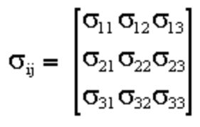
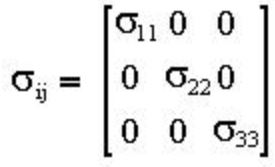
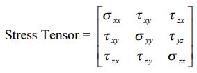
One commonly used method for analyzing stress in three-dimensional objects is the use of stress tensors. A stress tensor is a mathematical representation of stress that takes into account the stress components in all three dimensions. By using stress tensors, engineers can calculate and analyze stress in various directions and planes, providing valuable insights into the behavior of materials.

In conclusion, stress is a fundamental concept in materials science and engineering. It helps engineers understand how materials will behave under different loads and conditions. By considering different types of stress, such as principal stress and shear stress, engineers can accurately analyze the strength and stability of structures. In three-dimensional objects, stress analysis becomes more complex, requiring the use of stress tensors to calculate stress in different directions and planes.

How to Calculate Principal Stress from Principal Strain?

To calculate the level of stress on a structure, strain is measured.

The stress(in magnitude and direction) acting on a body can be determined by using the measured strain and certain properties of material like Modulus of Elasticity and Poisson’s Ratio.

In comparison to measure the normal strains on the surface of a body, it is quite difficult to measure normal and shear stresses acting on a body mostly at a point.

If we can measure the normal strains at a point, it is possible to find out the magnitude of principal strains as well as their directions. Now Principal stresses acting on a material which is obeying Hooke’s law can be determined from the measured principal strains.

The methods applied for strain measurement are as follows:

  • Direct: Electrical type gauges are used which follow resistive, capacitive, inductive or photoelectric principles.
  • Indirect: Optical methods are used for example holographic interferometry, photoelasticity etc.

A strain gauge is capable only of measuring strain in the direction in which gauge is oriented. 2. There is no direct way to measure the shear strain or to directly measure the principal strains as directions of principal planes are not generally known.

The main drawback of using a strain gauge is it can measure the strain only in the direction of its orientation. Since the direction of the principal planes are generally unknown, we cannot get a direct way to measure shear strain or principal strains.

To measure strain in three direction which is necessary for strain analysis in biaxial state we prefer strain rosettes where strain gauges are arranged in three directions. Different types of rosettes are available depending upon the arrangement of gauges.

A rectangular strain rosette consists of three strain gauges arranged as follows:-

dia6 1
A rectangular strain rosette; Image credit: nitsri.ac.in
how to calculate principal stress
Rosette Analysis; Image Credit: rosetteanalysis

If in stress measurement the directions of principal stress are unknown, a triaxial rosette gage is used to find out the strain values and using the following equations Principal stress can determined.

Consider ∈a→∈b→∈c as the forward direction, angleθ is angle of maximum principal strain to the ∈a axis when ∈c>∈b angle of minimum principal strain to the ∈a axis when ∈a<∈c. Comparison between ∈a and c in magnitude includes plus and minus signs

Maximum principal strain,

2%5B%5Cepsilon%20a+%5Cepsilon%20c+%5Csqrt%7B2%7B%28%5Cepsilon%20a %5Cepsilon%20b%29%5E%7B2%7D+%28%5Cepsilon%20b %5Cepsilon%20c%29%5E%7B2%7D%7D%7D%5D

Minimum principal strain

2%5B%5Cepsilon%20a+%5Cepsilon%20c %5Csqrt%7B2%7B%28%5Cepsilon%20a %5Cepsilon%20b%29%5E%7B2%7D+%28%5Cepsilon%20b %5Cepsilon%20c%29%5E%7B2%7D%7D%7D%5D

Direction of principal strain (from εa axis)

2%5Ctan%5E%7B 1%7D%5B%5Cfrac%7B2%5Cepsilon%20b %5Cepsilon%20a %5Cepsilon%20c%7D%7B%5Cepsilon%20a %5Cepsilon%20c%7D%5D

Maximum shearing strain

gif

Now Maximum Principal Stress,

eq1 2

Now Minimum Principal Stress,

eq2 3

Maximum shearing stress

eq3

v=Poisson’s ratio E:Young’s modulus

How to Calculate Principal Stresses from Stress Tensor?

If we consider a point as an infinitely small cube. Each face of the cube is represented by three separate stress vectors which are nothing but the stresses acted on each face.

In this way the total number of stresses act on the whole cube can be expressed by nine stress vectors inside a matrix . This stress matrix with nine stress vectors is known as the Stress Tensor.

dia1
Stress at a point; Image credit: geosci.usyd
Capture2

If the cube is in equilibrium, then it follows that

σ12 = σ21

σ13 = σ31

σ32 = σ 23

Six independent components are available in the stress tensor and it is symmetric in nature. If the cube is slanted keeping in mind that the major stress becomes normal to one of the planes and also no shear stresses are acting, in that condition the stress tensor can be represented as follows:

Capture3 1

σ11,σ22,σ33

Here are known as Principal Stresses.

The mean stress is simply the average of three stresses.

σm = (σ1+σ2+σ3)/3

How to Calculate 1st Principal Stress?

Using 1st Principal stress we can get the value of stress that is normal to a plane where the value of shear stress is zero.

The idea of the maximum tensile stress experienced by a part under a loading condition can get from 1st Principal Stress.

The normal and shear stress acting on the right face of the plane make up one point, and the normal and shear stress on the top face of the plane make up the second point.

The largest value of of sigma is the first principal stress, and the smallest value of sigma is the second principal stress.

principalstress mohrcirclesigns
1 st Principal Stress; Image credit:mechanics-of-materials-stress-transformation

How to calculate Principal Stress in 3D?

In case of 3D , the x,y and z are the orthogonal directions and we can consider one normal stress and two shear stresses are there. We can define the stress state at a point in 3D as shown below:

dia1 1
Stress at a point; Image credit: geosci.usyd

We can also represent it with the help of a stress tensor

dia2 2

If we go for a definite orientation of xyz axis, denoted by the directions 1,2 and 3, then only normal stresses will act and shear stresses will disappear.

These normal stresses are called Principal Stresses S1,S2 and S3.

dia 3 3
Orientation of orthogonal axis;Image credit: web.njit.edu

The values of the three principal normal stresses (S1, S2 & S3) can be found from the three real roots of S of the following cubic equation:

 S1,S2 and S3 can be found from the three real roots of S

gif

The values of S1, S2 & S3 should include the maximum and minimum normal stresses and S1, S2 & S3 could be positive, zero or negative.

How to Calculate Minor Principal Stresses?

The normal stresses acting on a principal plane is known as principal stresses: Major Principal Stress and Minor Principal Stress.

Minor principal stress gives the minimum value of principal stress and major principal stress gives the maximum value of the principal stress. Using Mohr’s circle method we can calculate the major and minor principal stresses.

dia 5 1
Image Credit: careercouncillor

Considering a stress system where figure ABCD represent a small element of a material.

Here σx, σy = Normal stresses (may be tensile or compressive)due to direct force or bending moment.

τ = shear stress due to direct shear force or torsion

gif

are complementary and

gif

Assume that σn is the normal stress and τ is the shear stress on a plane at an angle T.

At an equilibrium condition,

Normal stress, σn = x + σy)/2 + x – σy)/2 cos2θ + τxysin2θ

And Shear stress, τ = x – σy)/2 sin2θ – τxycos2θ

Above equations are the transformation equations and they don’t depend on material properties and valid for both elastic and inelastic behaviour.

If we locate the position of principal planes, where shear stress is zero, we have

δσn/δθ = 0

Here σn = (σx + σy)/2 + (σx – σy)2cos2θ +τxySin2θ

tan2θp = 2τxy(σx – σy)

θp is the angle of Principal Plane

Now Principal Stresses are

Major Principal Stress,

Minor Principal Stress,

y under different loading conditions.

The Interplay between Principal and Shear Stress

A. How Principal and Shear Stress Interact

In the field of stress analysis, understanding the interplay between principal and shear stress is crucial. When an object is subjected to external forces, it experiences stress, which is the measure of the internal forces within the material. Stress can be categorized into different types, including principal stress and shear stress.

Principal Stress: Principal stress refers to the maximum and minimum values of normal stress that act on a material in three dimensions. These principal stresses are important because they dictate the failure or deformation of a material. The maximum principal stress represents the highest tensile or compressive stress, while the minimum principal stress represents the lowest tensile or compressive stress.

Shear Stress: Shear stress, on the other hand, is the stress that acts parallel to a given plane within a material. It is responsible for the deformation or shearing of the material. Shear stress is calculated by dividing the force applied parallel to the plane by the area of the plane.

The interplay between principal and shear stress can be understood by examining the stress transformation equations. These equations allow us to determine the normal and shear stresses acting on any plane within a material.

When a material is subjected to external forces, the stress on a particular plane can be resolved into normal and shear components. The normal stress acts perpendicular to the plane, while the shear stress acts parallel to the plane. By analyzing the stress transformation equations, we can determine how the principal and shear stresses change as we rotate the plane of interest.

B. The Importance of Accurate Stress Calculations

Accurate stress calculations are essential in various fields, including mechanical engineering, material science, and structural analysis. Understanding the magnitude and direction of stress within a material helps engineers design structures that can withstand the applied loads.

By calculating the principal stress, engineers can identify the critical areas within a structure where failure is most likely to occur. This information allows them to make informed decisions regarding material selection, design modifications, and stress concentration mitigation.

One commonly used method for calculating principal stress is through the use of Mohr’s Circle. Mohr’s Circle is a graphical representation of stress transformation that simplifies the calculation process. By plotting the normal and shear stresses on a graph, engineers can determine the principal stresses and the orientation of the planes on which they act.

Another approach to calculating principal stress is through the use of stress tensors. A stress tensor is a mathematical representation of stress that allows for the calculation of stress components in any direction. By utilizing the stress tensor, engineers can determine the principal stresses and their associated directions.

Accurate stress calculations are vital in ensuring the safety and reliability of structures. By understanding the interplay between principal and shear stress and employing accurate stress calculation methods, engineers can design structures that can withstand the forces they will encounter in their operational lifespan.

In conclusion, the interplay between principal and shear stress is a fundamental aspect of stress analysis. By understanding how these two types of stress interact, engineers can accurately calculate stress values and make informed decisions regarding material selection, design modifications, and stress concentration mitigation. Accurate stress calculations are crucial in ensuring the safety and reliability of structures in various fields, including mechanical engineering, material science, and structural analysis.

Conclusion

In conclusion, calculating principal stress is an essential step in analyzing the behavior of materials under different loading conditions. By determining the principal stresses, engineers and scientists can gain valuable insights into the strength and stability of structures and components. The process involves finding the maximum and minimum normal stresses acting on a material, and then using these values to calculate the principal stresses. This information is crucial for designing safe and efficient structures, predicting failure points, and optimizing material usage. By understanding how to calculate principal stress, engineers can make informed decisions and ensure the integrity and reliability of their designs. So, the next time you encounter a problem involving stress analysis, remember to calculate the principal stresses and unlock a wealth of valuable information.

Frequently Asked Questions

1. How to calculate principal stress in 3D?

Principal stress in 3D can be calculated using the stress tensor and the principles of stress transformation. This involves finding the eigenvalues of the stress tensor, which represent the principal stresses. The stress tensor is a 3×3 matrix that contains the normal and shear stress components on the three orthogonal faces of a differential element.

2. How to calculate shear stress in threads?

Shear stress in threads can be calculated using the formula: τ = F / (π * d * n), where τ is the shear stress, F is the force applied, d is the nominal diameter of the screw, and n is the number of engaged threads. This formula assumes that the load is evenly distributed among the threads.

3. How to calculate shear stress in a beam?

Shear stress in a beam can be calculated using the formula: τ = VQ / It, where τ is the shear stress, V is the shear force, Q is the first moment of area, I is the moment of inertia, and t is the thickness of the beam at the point of interest.

4. How to calculate shear stress from tensile strength?

Shear stress can be calculated from tensile strength using the formula: τ = σ / 2, where τ is the shear stress and σ is the tensile strength. This formula is based on the maximum distortion energy theory, which assumes that failure occurs when the strain energy per unit volume due to shear stress exceeds the strain energy due to tensile stress.

5. How to calculate principal stresses?

Principal stresses can be calculated using Mohr’s Circle, a graphical method used in the field of stress analysis. The principal stresses are the maximum and minimum values of normal stress that act on a particular point in a material.

6. How to calculate shear stress in COMSOL?

In COMSOL, shear stress can be calculated using the built-in stress analysis module. This module allows you to define the material properties, load conditions, and boundary conditions, and then solves the stress equations to calculate the shear stress distribution in the material.

7. How to calculate shear stress?

Shear stress can be calculated using the formula: τ = F / A, where τ is the shear stress, F is the force applied, and A is the area over which the force is applied. This formula assumes that the force is applied parallel to the area.

8. How to calculate principal stress?

Principal stress can be calculated using the stress transformation equations, which are derived from the principles of equilibrium and compatibility. The principal stresses are the maximum and minimum values of normal stress that act on a particular point in a material.

9. How to calculate shear stress in a plate?

Shear stress in a plate can be calculated using the formula: τ = V / A, where τ is the shear stress, V is the shear force, and A is the area of the plate. This formula assumes that the force is applied parallel to the area of the plate.

10. How to calculate shear stress of a shaft?

Shear stress in a shaft can be calculated using the formula: τ = T*r / J, where τ is the shear stress, T is the applied torque, r is the radius of the shaft, and J is the polar moment of inertia of the shaft. This formula is based on the torsion formula, which relates the torque applied to a shaft to the resulting shear stress.

Mass Flow Rate Vs Flow Rate: Comparative Analysis And Facts

Proper understanding of Mass Flow Rate Vs Flow Rate is necessary to decide which flow instrument is right for a particular application.

Mass Flow Rate can be defined as the mass of a fluid, it may be liquid or gas, flows through a cross sectional area within a time period. Similarly Flow Rate can be defined as the volume of a fluid which may be liquid or gas flows through a given cross sectional area per unit time.

Why Mass flow and volume flow rate measurement are important facts in a process industry?

The accurate measurement of the fluid flowing through a duct, either it may be a gas or liquid is a critical parameter in many industries.

  • Decision of right fluid at accurate amount and right time is mandatory to run an operation.
  • Accurate flow measurement influences the product quality, health and safety.
  • A devastating situation may occur due to wrong measurement of flow during an operation.
  • It also helps in supervision of assets by regulating the fluid movement or maintaining a balanced amount in the tank.
  • Income of an industry depends on the correct measurement of mass and volume flow rate.

What is Mass Flow Rate?

Mass is the how much matter present in a substance and often expressed in weight i.e. gm, kg, pounds, tonnes etc.

Mass Flow Rate is the number of molecules of a fluid  pass through the cross sectional area of a pipe within a particular time period. It is denoted by (m dot).

  ṁ=mass/time=m/t

Commonly used units of mass flow rate are kilogram/second or pounds/hour.

Mass flow can be represented by the following formula:

Mass=density  x volume=density x Area x velocity

ṁ = ρ A v

Where

ṁ = mass flow rate in kg/s

ρ = density in kg/m3

A = area/section of pipe or a channel in m2

v =velocity in m/s

What is Volume Flow Rate ?

Volume Flow Rate or rate of fluid gives the flow of some volume of any fluid through a cross sectional area per unit time and is denoted by Q or V.

Volume Flow rate also known as actual flow rate indicates the volume of fluid flowing through a duct or pipe per unit time. Different units of Flow rate are cubic metres per second, cubic centimetres per minute, litre per minute etc.

If we consider a kitchen faucet, the amount of water( in litre or cubic metre) flows through the faucet within a particular time period ( in second or minute),then this amount of water flow can be considered as the volume flow rate. This term is always applicable to gases and liquids.

Volumetric flow can be represented by the following formula:

Q=V /t

Where

Q= Volume flow rate m3/s or L/s .

V=Volume of fluid in litre or cubic metre

gif

=Average velocity of flow( Average value is considered because at every part velocity of the fluid is not same)m/s

A=Cross sectional area occupied by the moving fluid m2

gif

=Cross sectional area x Average velocity

Mass Flow Rate Vs Flow Rate
Volume Flow Rate

Mass Flow Rate Vs Flow Rate

The concept of Mass Flow Rate vs Flow Rate is the important parameter for ensuring safe, smooth and cost effective running of fluid control processes.

Difference between Mass Flow rate and Volume Flow Rate

Mass Flow RateVolume Flow Rate
Actual mass of a fluid which travels through a measuring instrument per unit of timeVolume of fluid that passes through a measuring instrument per unit time.
Preferable in case of high accuracy with a high pressure ratingGenerally preferred when high accuracy isn’t necessary.
There is no change in mass flow rate with changing pressure and temperature.Changes in Flow rate occurs with pressure and temperature is changed.
Formula for mass flow rate, ṁ = Density x cross sectional area x velocity  Formula for volume flow rate, Q=Cross sectional area x Av. velocity
Mass flow is measured in kilogram/secondVolume flow rate is measured in litre/second or cubic metre/second.
Table: Mass Flow Rate Vs Flow Rate

Relationship between Mass Flow rate and Volume Flow Rate

We know that,

m = ρ.V Eq1

Where m=mass

ρ=density

V=volume

If we multiply both sides of Eq(1) with time, t, then we get

m/t = ρ.V/t

ṁ = ρ.Q Eq2

Where ṁ=mass flow rate

Q= Volume flow rate

but Q= Volume flow rate= Cross sectional area(A) x Average velocity

From Eq (2)

gif

Eq3

Comparison of Mass Flow rate Vs Flow Rate Measurement

The cost between mass flow measurement and volume flow measurement is quite significant.

There is a wide difference between the mass flow rate and volume flow rate measuring devices in terms of cost, generally mass flow meter are costly in comparison to volume flow meters.

 But extra expenditure is associated with volume flow meters since we have to purchase and install some temperature and pressure measuring devices to get a correct value.

An advantage associated with mass flow rate measurement is when mass flow rate of a fluid is measured, the mass or weight of the fluid does not fluctuate with the change of pressure and temperature.

From mass flow measuring devices we get more reliable and precise data in comparison to flow rate measuring devices.

Depending on the requirement (like want to measure a set of volume or the number of molecules) of application we decide to use mass flow or volume flow rate of a fluid.

Mass flow rate remains constant regardless of change in pressure and temperature. Sometimes mass flow instruments are preferred over volume flow instruments due to the ability of measuring and controlling  the movement of gas molecules accurately during in and out of a process.

Examples of Mass Flow Applications are

Gas mixing applications,custody transfer applications, manufacturing optical fibres, mass flow is used to regulate oxygen and CO2 levels in bioreactors,mass flow devices are used in the burner control application etc.

 Examples of volumetric flow measurement are

To monitor ambient air and to maintain industrial hygiene are the two applications that make use of volumetric flow. The main aim in each of the application to compute the number of air particles in a specific volume of air under certain ambient conditions.

Mass Flow Devices and volumetric Flow Devices

The principle used to measure flow also depends upon the service of the fluid to be measured.

The principles of flow measurement either in mass or volumetric basis varies widely and so are their accuracy level and cost of the measuring device.

Majority of the flow devices measure the flow by using the principle of Bernoulli’s theorem that calculates the velocity of fluid by measuring the pressure drop between two successive points in the flow path.

The differential pressure (DP Type) flow-meters are most widely used flow measuring devices used in the industry, where the fluid is allowed to pass through a flow orifice plate and differential pressure across the orifice is measured to calculate the flow.

The venturi flow-meters and pitot-tube flow meters too work on similar principle.

The only device that measures the flow by measuring its volume is the positive displacement or PD meter. This device has quite good accuracy levels and used widely in custody transfer applications majorly in oil and gas service.

The following devices measure volumetric flow:

  1. Positive displacement meters
  2. Turbine flow meters
  3. Orifice plates
  4. Venturis
  5. Vortex meters
  6. Pitot tubes
  7. Rotometers
dia 3 2
Venturis;Image Credit : venturis
dia 4
Rotometer ; Image Credit: flow-meters.biz

Compared to Volumetric flow, the number of technology available to measure directly the mass flow is limited. The most common among them is the coriolis meter, which measure the fluid vibration as it passes though the tube.

The thermal mass flow meter works on the principle of measurement of heat flow rate across the flowing fluid.

Ultrasonic flow-meters works on the principle of measurement of velocity of sound waves in the fluid to measure the fluid velocity.

The following devices measure mass flow:

  1. Coriolis flow meters
  2. Thermal mass flow meters
  3. Ultrasonic meters (indirect mass flow)
dia5 1
Ultrsonic Meters;Image credit: elprocus

Specific Enthalpy Vs Enthalpy: Comparative Analysis and FAQs

Capture 5 300x253 1

Specific Enthalpy vs Enthalpy

Enthalpy is a fundamental concept in thermodynamics that measures the total heat content of a system. It is often used to describe the energy changes that occur during chemical reactions or phase transitions. However, there is another term closely related to enthalpy known as specific enthalpy. While both terms are used to quantify energy changes, they have distinct differences in their definitions and applications. In this article, we will explore the differences between specific enthalpy and enthalpy, and understand how they are used in various fields of science and engineering. So, let’s dive in and unravel the mysteries behind these two important concepts in thermodynamics.

Key Takeaways

  • Enthalpy is a thermodynamic property that represents the total heat content of a system, while specific enthalpy is the enthalpy per unit mass of a substance.
  • Specific enthalpy is useful in engineering applications as it allows for more accurate calculations and comparisons between different substances.
  • Enthalpy is typically measured in units of energy, such as joules or calories, while specific enthalpy is measured in units of energy per unit mass, such as joules per kilogram.
  • The specific enthalpy of a substance can be calculated by dividing the enthalpy by the mass of the substance.
  • Both enthalpy and specific enthalpy are important concepts in thermodynamics and are used to analyze and design various processes and systems.

Enthalpy vs Specific Enthalpy

Enthalpy: Definition and Components (Internal Energy and Pressure-Volume Work)

Enthalpy is a fundamental concept in thermodynamics that helps us understand the energy content of a system. It is denoted by the symbol “H” and is defined as the sum of the internal energy (U) and the product of pressure (P) and volume (V) of the system. In other words, enthalpy accounts for both the heat energy and the work done by the system.

The internal energy represents the total energy stored within the system, including the kinetic and potential energies of its particles. On the other hand, the pressure-volume work accounts for the energy transferred to or from the system due to changes in its volume under constant pressure.

Specific Enthalpy: Definition as Enthalpy per Unit Mass

Capture 5
.nuclear-power.com

Specific enthalpy, denoted as “h,” is the enthalpy per unit mass of a substance. It is obtained by dividing the enthalpy (H) of the system by its mass (m). Specific enthalpy allows us to analyze the energy content of a substance on a per-unit-mass basis, which is particularly useful in engineering and thermodynamic calculations.

By expressing enthalpy in terms of mass, specific enthalpy enables us to compare the energy content of different substances or different amounts of the same substance.

Comparison between Enthalpy and Specific Enthalpy

The main difference between enthalpy and specific enthalpy lies in their units and the way they are used. Enthalpy is an extensive property, meaning it depends on the size or amount of the system. On the other hand, specific enthalpy is an intensive property, which remains constant regardless of the system size.

Enthalpy allows us to analyze the total energy content of a system, taking into account both the internal energy and the work done. It is commonly used in thermodynamic calculations, such as determining the heat transfer in chemical reactions or phase changes.

Specific enthalpy, on the other hand, provides a more detailed analysis by considering the energy content on a per-unit-mass basis. It is particularly useful in engineering applications, such as calculating the energy required for heating or cooling a specific mass of a substance.

Units of Measurement for Enthalpy and Specific Enthalpy

Enthalpy is typically measured in units of energy, such as joules (J) or calories (cal). The SI unit for enthalpy is joule, while the calorie is commonly used in the field of chemistry.

Specific enthalpy is expressed in the same units as enthalpy but divided by mass. Therefore, the units for specific enthalpy are joules per kilogram (J/kg) or calories per gram (cal/g).

To summarize, enthalpy and specific enthalpy are both important concepts in thermodynamics. Enthalpy provides a comprehensive analysis of the energy content of a system, while specific enthalpy allows for a more detailed examination on a per-unit-mass basis. Understanding these concepts is crucial for engineers, scientists, and anyone working with energy systems.

Specific Enthalpy of Steam Water System

The specific enthalpy of a steam water system is a crucial thermodynamic property that helps us understand the energy content of the system. It is defined as the amount of heat energy per unit mass of a substance, and it plays a significant role in various engineering applications, particularly in the field of thermodynamics.

Specific Enthalpy Values for Vaporization and Saturation of Water

When water undergoes a phase change from a liquid to a vapor state, it requires a certain amount of energy. This energy is known as the specific enthalpy of vaporization. It represents the heat energy needed to convert one unit mass of liquid water into vapor at a given temperature and pressure.

Similarly, the specific enthalpy of saturation refers to the energy content of water when it exists in a saturated state. In this state, water is at the boiling point corresponding to a specific pressure. The specific enthalpy of saturation is the sum of the specific enthalpy of liquid water and the specific enthalpy of vaporization.

Calculation of Specific Enthalpy for Saturated Steam at Atmospheric Pressure

To calculate the specific enthalpy for saturated steam at atmospheric pressure, we need to consider the specific enthalpy of liquid water and the specific enthalpy of vaporization. The specific enthalpy of liquid water can be determined using tables or equations based on temperature. The specific enthalpy of vaporization can also be obtained from tables or correlations.

By adding the specific enthalpy of liquid water and the specific enthalpy of vaporization, we can determine the specific enthalpy of saturated steam at atmospheric pressure. This value represents the energy content of steam in its saturated state.

Increase in Specific Enthalpy with System Pressure

As the pressure of a steam water system increases, the specific enthalpy also increases. This is because higher pressures require more energy to convert water into steam. The specific enthalpy of steam at a given pressure is higher than that at atmospheric pressure due to the additional energy required for vaporization.

The increase in specific enthalpy with system pressure is an important consideration in various industrial processes, such as power generation and steam-driven machinery. Understanding the relationship between pressure and specific enthalpy allows engineers to design efficient systems and optimize energy usage.

Calculation of Specific Enthalpy for Superheated Steam

Superheated steam refers to steam that has been heated beyond its saturation point. To calculate the specific enthalpy for superheated steam, we need to consider the specific enthalpy of saturated steam and the specific enthalpy of superheating.

The specific enthalpy of saturated steam can be determined as mentioned earlier. The specific enthalpy of superheating represents the additional energy required to heat the steam beyond its saturation point. This value can be obtained from tables or correlations based on the temperature and pressure of the superheated steam.

By adding the specific enthalpy of saturated steam and the specific enthalpy of superheating, we can determine the specific enthalpy of superheated steam. This value represents the total energy content of steam in its superheated state.

Molar Enthalpy vs Specific Enthalpy

Definition of Molar Enthalpy and Specific Enthalpy

Enthalpy is a fundamental concept in thermodynamics that measures the total energy of a system. It is denoted by the symbol “H” and is often used to describe heat transfer and energy changes in chemical reactions. Molar enthalpy and specific enthalpy are two related but distinct concepts that are commonly used in different contexts.

Molar enthalpy, also known as molar heat capacity, is the amount of heat required to raise the temperature of one mole of a substance by one degree Celsius. It is represented by the symbol “Cp” and has units of joules per mole per degree Celsius (J/mol·°C). Molar enthalpy takes into account the mass of the substance and is used to calculate the enthalpy change in reactions.

On the other hand, specific enthalpy, also known as specific heat capacity, is the amount of heat required to raise the temperature of a unit mass of a substance by one degree Celsius. It is represented by the symbol “cp” and has units of joules per kilogram per degree Celsius (J/kg·°C). Specific enthalpy is used for heat balance calculations in engineering and is independent of the mass of the substance.

Differences between Molar Enthalpy and Specific Enthalpy

The main difference between molar enthalpy and specific enthalpy lies in the units of measurement and the quantity being considered. Molar enthalpy is expressed in terms of moles of a substance, while specific enthalpy is expressed in terms of kilograms of a substance.

Molar enthalpy takes into account the mass of the substance and is used to calculate the enthalpy change in reactions. It is particularly useful in chemical reactions where the quantities involved are often measured in moles. Specific enthalpy, on the other hand, is used for heat balance calculations in engineering, where the focus is on the energy required to heat or cool a given mass of a substance.

Molar Enthalpy used for calculating enthalpy change in reactions

Molar enthalpy is commonly used in chemical reactions to calculate the enthalpy change, also known as the heat of reaction. The enthalpy change is the difference in enthalpy between the products and the reactants in a chemical reaction. By knowing the molar enthalpies of the reactants and products, it is possible to calculate the enthalpy change using the principle of conservation of energy.

For example, in the combustion of methane (CH4), the molar enthalpy of methane is -890.3 kJ/mol, and the molar enthalpy of carbon dioxide (CO2) is -393.5 kJ/mol. By subtracting the molar enthalpy of the reactants from the molar enthalpy of the products, the enthalpy change of the reaction can be determined.

Specific Enthalpy used for heat balance calculations in engineering

Specific enthalpy is widely used in engineering for heat balance calculations. Heat balance calculations involve determining the amount of heat energy required to heat or cool a given mass of a substance. Specific enthalpy allows engineers to calculate the energy requirements for various processes, such as heating water or cooling air.

For example, in HVAC (Heating, Ventilation, and Air Conditioning) systems, specific enthalpy is used to calculate the energy required to heat or cool air as it flows through the system. By knowing the specific enthalpy of the incoming and outgoing air, engineers can determine the amount of energy needed to achieve the desired temperature change.

Units of measurement for Molar Enthalpy and Specific Enthalpy

Molar enthalpy is measured in joules per mole per degree Celsius (J/mol·°C), while specific enthalpy is measured in joules per kilogram per degree Celsius (J/kg·°C). These units reflect the different quantities being considered – moles for molar enthalpy and kilograms for specific enthalpy.

Calculation of total enthalpy change using Molar Enthalpy and Specific Enthalpy

To calculate the total enthalpy change in a system, both molar enthalpy and specific enthalpy can be used. The molar enthalpy is used to determine the enthalpy change at the molecular level, while the specific enthalpy is used to determine the enthalpy change at the mass level.

The total enthalpy change can be calculated by multiplying the molar enthalpy by the number of moles involved in the reaction and adding it to the product of the specific enthalpy and the mass of the substance. This allows for a comprehensive understanding of the energy changes occurring in a system.

Different Types of Enthalpy Change

Enthalpy change refers to the amount of heat energy transferred during a chemical reaction or physical process. There are various types of enthalpy changes that occur in different scenarios. Let’s explore some of the most common types of enthalpy changes.

Explanation of Various Types of Enthalpy Changes

  1. Enthalpy of Reaction: The enthalpy change associated with a chemical reaction is known as the enthalpy of reaction. It represents the difference in enthalpy between the products and the reactants. This value can be positive or negative, depending on whether the reaction is exothermic (releases heat) or endothermic (absorbs heat).

  2. Enthalpy of Combustion: The enthalpy change that occurs during the combustion of a substance is called the enthalpy of combustion. It measures the heat energy released when a substance reacts with oxygen to form carbon dioxide and water.

  3. Enthalpy of Formation: The enthalpy change when one mole of a compound is formed from its constituent elements in their standard states is known as the enthalpy of formation. It provides information about the stability and energy content of the compound.

  4. Enthalpy of Neutralization: The enthalpy change that occurs when an acid reacts with a base to form a salt and water is called the enthalpy of neutralization. It represents the heat energy released or absorbed during the neutralization process.

  5. Enthalpy of Solution: The enthalpy change associated with the dissolution of a solute in a solvent is known as the enthalpy of solution. It measures the heat energy released or absorbed when a solute dissolves to form a solution.

  6. Enthalpy of Fusion: The enthalpy change when a substance changes from a solid to a liquid state at its melting point is called the enthalpy of fusion. It represents the heat energy required to overcome the intermolecular forces holding the solid together.

  7. Enthalpy of Sublimation: The enthalpy change when a substance changes directly from a solid to a gaseous state without passing through the liquid state is known as the enthalpy of sublimation. It measures the heat energy required to overcome the forces holding the solid together and convert it into a gas.

  8. Enthalpy of Vaporization: The enthalpy change when a substance changes from a liquid to a gaseous state at its boiling point is called the enthalpy of vaporization. It represents the heat energy required to overcome the intermolecular forces holding the liquid together.

  9. Enthalpy of Mixing: The enthalpy change that occurs when two or more substances are mixed together is known as the enthalpy of mixing. It measures the heat energy released or absorbed during the mixing process.

By understanding these different types of enthalpy changes, we can gain insights into the energy transformations that occur during chemical reactions and physical processes. These values play a crucial role in various scientific and engineering applications, such as designing efficient energy systems and understanding the thermodynamics of chemical reactions.

Favorable Enthalpy

Enthalpy is a fundamental concept in thermodynamics that helps us understand the energy changes that occur during chemical reactions. It plays a crucial role in determining whether a reaction is favorable or not. In this section, we will explore the relationship between enthalpy change and reaction favorability, as well as introduce the concept of Gibbs free energy.

Favorability of a reaction based on enthalpy change

The enthalpy change of a reaction, often denoted as ΔH, is a measure of the heat energy absorbed or released during a chemical reaction. It represents the difference in enthalpy between the products and the reactants. By analyzing the sign and magnitude of ΔH, we can determine whether a reaction is exothermic or endothermic.

An exothermic reaction releases heat energy to the surroundings, resulting in a negative ΔH value. On the other hand, an endothermic reaction absorbs heat energy from the surroundings, leading to a positive ΔH value. The magnitude of ΔH indicates the amount of heat energy involved in the reaction.

Relationship between enthalpy change and entropy change

Entropy, denoted as ΔS, is a measure of the disorder or randomness in a system. It accounts for the number of ways in which the particles of a system can be arranged. A positive ΔS value indicates an increase in disorder, while a negative ΔS value suggests a decrease in disorder.

The relationship between enthalpy change (ΔH) and entropy change (ΔS) is described by the equation:

ΔG = ΔH – TΔS

where ΔG is the Gibbs free energy change and T is the temperature in Kelvin. The Gibbs free energy change determines the spontaneity of a reaction. If ΔG is negative, the reaction is spontaneous and favorable. If ΔG is positive, the reaction is non-spontaneous and unfavorable. If ΔG is zero, the reaction is at equilibrium.

Gibbs free energy (ΔG) is a thermodynamic potential that combines the effects of enthalpy change (ΔH) and entropy change (ΔS) to determine the spontaneity of a reaction. It provides a more comprehensive understanding of reaction favorability compared to enthalpy alone.

The equation ΔG = ΔH – TΔS tells us that for a reaction to be favorable, the enthalpy change must be negative (exothermic) and the entropy change must be positive (increase in disorder). However, the temperature also plays a crucial role. At low temperatures, a negative enthalpy change dominates, making the reaction favorable. At high temperatures, a positive entropy change dominates, making the reaction favorable.

Frequently Asked Questions

1. Why are enthalpy values different?

Enthalpy values can vary depending on the specific process or reaction being considered. Factors such as temperature, pressure, and the presence of other substances can influence the enthalpy of a system, leading to differences in the measured values.

2. Is enthalpy the same as specific heat?

No, enthalpy and specific heat are different properties. Enthalpy is a measure of the total energy of a system, including both its internal energy and the work done on or by the system. Specific heat, on the other hand, is a measure of the amount of heat required to raise the temperature of a unit mass of a substance by a certain amount.

3. What is the difference between specific heat capacity and enthalpy?

Specific heat capacity refers to the amount of heat required to raise the temperature of a unit mass of a substance by a certain amount. Enthalpy, on the other hand, is a measure of the total energy of a system, including both its internal energy and the work done on or by the system. While specific heat capacity is a property of a substance, enthalpy is a property of a system.

4. Why is the experimental enthalpy higher than the theoretical value?

There can be several reasons for the experimental enthalpy to be higher than the theoretical value. Experimental errors, incomplete reactions, side reactions, and impurities in the reactants can all contribute to the deviation between the experimental and theoretical enthalpy values.

5. What is the difference between standard enthalpy and enthalpy?

Standard enthalpy refers to the enthalpy change that occurs under standard conditions, which typically include a temperature of 25°C and a pressure of 1 bar. Enthalpy, on the other hand, is a more general term that refers to the total energy of a system, including both its internal energy and the work done on or by the system.

6. What is specific enthalpy?

Specific enthalpy is the enthalpy per unit mass of a substance. It is a measure of the total energy of a unit mass of a substance, including both its internal energy and the work done on or by the substance.

7. What is the difference between enthalpy change and standard enthalpy change?

Enthalpy change refers to the difference in enthalpy between the reactants and the products in a chemical reaction. It can be positive (endothermic) or negative (exothermic). Standard enthalpy change, on the other hand, refers to the enthalpy change that occurs under standard conditions, typically at a temperature of 25°C and a pressure of 1 bar.

8. What is the difference between specific enthalpy and enthalpy?

Specific enthalpy refers to the enthalpy per unit mass of a substance, while enthalpy is a more general term that refers to the total energy of a system. Specific enthalpy takes into account the mass of the substance, whereas enthalpy does not.

9. What is the difference between enthalpy of formation and enthalpy of reaction?

Enthalpy of formation refers to the enthalpy change that occurs when one mole of a compound is formed from its constituent elements in their standard states. Enthalpy of reaction, on the other hand, refers to the enthalpy change that occurs in a chemical reaction, regardless of the formation of new compounds.

10. What is the difference between enthalpy of mixing and enthalpy of solution?

Enthalpy of mixing refers to the enthalpy change that occurs when two or more substances are combined to form a mixture. Enthalpy of solution, on the other hand, refers to the enthalpy change that occurs when a solute is dissolved in a solvent to form a solution.

3 Unilateral Tolerance Examples: Explanations And Detailed Facts

DIA 0

Unilateral Tolerance examples are generally observed in interchangeable manufacturing processes specially where precision fits are required.

A Unilateral Tolerance basically signifies a nominal size and either a plus or a minus tolerance. In Unilateral Tolerance the allowable size variation is only in one direction, it can be positive or negative and zero value is also permitted.

Tolerance or permissible variation of dimension is always allowed during machining of a mating component or any engineering parts to avoid high cost and long time consumption.

The permissible deviation of true dimension of a mating part without hindering any functional accuracy and useful for actual working is known as tolerance.

Tolerance zone indicates the difference between the upper and lower limit of deviation.

There different types of tolerances are listed below:

  • Unilateral Tolerance
  • Bilateral Tolerance
  • Compound Tolerance
  • Geometric Tolerance

Here we are going to discuss mainly about Unilateral Tolerance

Unilateral Tolerance Examples
Unilateral Tolerance;  Image Credit: home.iitk.ac.in

The diagram shows us that the tolerance lies only on one side of the basic size. It may be above or below the nominal dimension.

Some examples of Unilateral Tolerances are given below to get a clear idea:

  • 12.0mm +0/+0.5mm
  • 5.5″ +0.010″/+0.015″
  • 5.325″ +0/-0.002″
  • 7.1mm -0.5/-0.6mm

The above examples can be illustrated elaborately as below:

Nominal SizeBottom ToleranceTop Tolerance
12.0mm12.0mm12.5mm
5.5″5.51″5.515″
5.325″5.325″5.323″
7.1mm6.6mm6.5mm

What is Unilateral Tolerance?

During machining of mating parts Unilateral Tolerance assist the operators to calculate the deviation in a easy and simple way.

In Unilateral tolerance the variation from the original profile is only allowed in one direction i.e tolerance limits lie only above or below the basic size. Here the variation in dimension is permitted only in one direction, not in both the directions.

Unilateral Tolerance is most widely used especially in case of precision fits due to its simplicity in determining the deviations.

DIA 2
Unilateral tolerance;Image Credit: theengineerspost.

Example of Unilateral Tolerance for machining a shaft:

DIA 3 4

Here we try to achieve a diameter of 25 cm, known as basic or nominal size. The deviation from the basic size is permitted as +0.02 cm as upper limit and +0.01 cm as lower limit. Here the variation in dimension is allowed only in positive direction or above the basic size.

Basic size: 25 cm

Upper limit: 25+.02=25.02cm

Lower limit: 25+.01=25.01cm

DIA4 3
Unilateral Tolerance; Image Credit: getmyuni.azureedge.

How to calculate Cpk for Unilateral Tolerance?

Unilateral or one-sided tolerances impose only an upper limit or a lower limit on the process, and leave the specification unbounded on the other side.

The Process Capability Indices Cp & Cpk can be calculated by using the following formulae:

Cp = USL-LSL/6σ

gif
gif
gif

Where USL=Upper Specification Limit

LSL=Lower Specification Limit

0

The process capability index Cpk is used in manufacturing industry to calculate the ability of the process to meet customers’ expectations. In this competitive world to sustain in the market the good knowledge of Cp and Cpk value is a powerful strategy.

In general, higher the Cpk value, the better the product or process that means the process or the product has a higher ability to satisfy the customers. In other words an improvement in the process results a higher Cpk value.

Cpk is calculated by determining the difference between mean value and specification(upper and lower), then this difference is divided by 3 x standard deviation. The value obtained indicates the process capability, higher value means better product or process.

Cpk=Zmin/3

Zmin=Smaller of Zupper or Zlower

Zupper=[(USL-Mean)/Estimated sigma*]

Zlower=[(Mean-LSL)/Estimated sigma*]

Estimated sigma=average range/d2

In case of Unilateral Tolerance we have only one specification or tolerance either upper tolerance or lower tolerance. For example in our example we have only upper tolerance value but no lower tolerance.

In this case we can go for two options

  • Considering LSL as 0
  • Lower specification or tolerance is missing and calculation is done without considering it.

Let here USL=0.5

And estimated sigma=0.15

In case of the 1st option,

We consider LSL=0

Zupper = [0.5-0.0025/0.15] = 3.316

Zlower = [0.0025-0/0.15] = 0.01667

Zmin = 0.01667

Cpk = 0.01667/3 = 0.005

This value of Cpk i.e. 0.005 cann not satisfy a customer .

In case of the 2nd option,

Here we assume that lower specification or tolerance is missing, without LSL, obliviously Z lower value is also missing.

Zupper=3.316(from above)

Cpk=3.316/3=1.10

A Cpkof 1.10 is more realistic than one of 0.005.

From the above example it is clear that Cpk can be calculated when only one deviation exists, using only the available specification and the other one specification is considered as missing. Now consider either the upper limit( Zupper) or the lower limit( Zlower).

If we consider lower specification as zero it will give a lower value of Cpk which is not advisable.

How to convert Unilateral Tolerance to Bilateral Tolerance?

A bilateral tolerance is plus AND minus whereas a unilateral tolerance is a plus OR minus tolerance.

In case of Bilateral Tolerance variation from the true profile is permitted in both directions whereas in case of Unilateral Tolerance variation is allowed only in one direction.

DIA10
Unilateral Tolerance;Image Credit: https://ncet.co.in/

1
Bilateral Tolerance; Image Credit: https://ncet.co.in/

Let us consider an example of a Unilateral Tolerance is

2 1
DIA13 1
DIA12

Here Basic size: 40.0

Upper Tolerance:40.0+0.0=40.0

Lower Tolerance:40.0-0.5=39.5

Now if we try to convert this Unilateral Tolerance into Bilateral Tolerance, then it will be:

Divide the total tolerance by 2,   -0.5/2= -0.25

Determine the mean dimension,  40.0-0.25= 39.75

Now write as a bilateral tolerance  ,

For this new bilateral form

Basic size: 39.75

Upper Tolerance:39.75+.25=40.0

Lower Tolerance:39.75-0.25=39.5

We can convert Unilateral tolerance into Bilateral Tolerance keeping the Tolerance zone same and including both +ve and –ve tolerance.

How to find Unilateral Tolerance?

Unilateral Tolerance is a unequally disposed tolerance where deviations lie only in one direction of the nominal size.

Unilateral Tolerance consists of one nominal size or basic size and a plus or minus deviation. Using these values we can easily calculate the Unilateral Tolerance given for a component.

Considering an example of Unilateral Tolerance ,

1)

DIA 3 3

Basic size: 25 cm

Upper limit: 25+.02=25.02cm

Lower limit: 25+.01=25.01cm

Tolerance Zone=25.02-25.01=0.01cm

2)

DIA14

Basic size: 25 cm

Upper limit: 25-.01=24.90cm

Lower limit: 25-.02=24.80cm

Tolerance Zone=24.90-24.80=0.10cm

DIA15
Examples of Unilateral Tolerance;Image Credit: getmyuni.azureedge.

Types of Tolerance: Explanation, Comparative Analysis, Examples

Capture 1 2

Types of Tolerances used in a technical drawing mainly indicate the permissible amount of deviations from the original dimension.

Tolerance can be classified as follows

  • Unilateral Tolerance
  • Bilateral Tolerance
  • Compound Tolerance
  • Geometric Tolerance

Tolerance or permissible variation of dimension is always allowed during machining of a mating component or any engineering parts to avoid high cost and long time consumption.

 The permissible deviation of true dimension of a mating part without hindering any functional accuracy and useful for actual working is known as tolerance.

Unilateral Tolerance: In Unilateral tolerance the variation from the original profile is only allowed in one direction i.e tolerance limits lie only above or below the basic size. Here the variation in dimension is permitted only in one direction, not in both the directions.

Bilateral Tolerance: In Bilateral Tolerance the size of the part varies above and below the basic size, i.e. the variation in dimension is in both the directions.

Compound Tolerance: Compound Tolerance can be calculated by adding or subtracting multiple Tolerances associated with different dimensions. Compound Tolerance is derived by using different established Tolerances (for e.g. lateral, angular etc). 

types of tolerances
Compound Tolerance; Image Credit: htheengineerspost.com

From the above figure it is clear that Compound tolerance on I  is dependent on tolerances of L, h and θ.Here I is the combination of three tolerances .The minimum tolerance on ‘l’ will be corresponding to L-b, θ+∝ and h+c.

Geometric Tolerance: Geometrical tolerances are associated with certain geometrical features like flatness of a plane surface, straightness of a cylinder, squareness of a square shape, roundness etc.

While defining the tolerances of a complex structure requiring various tolerances in multiple dimensions, it is important to note the individual tolerance provided are kept on check so that, the cumulative effect of tolerance build-up doesn’t make the overall tolerance to be un undesirable range.

This is particularly true in case of specifying dimensional geometric tolerances which are frequently used to indicate the relationship of one part to another. This is also called positional tolerance which is a 3 dimensional geometric tolerance comprising of position, symmetry and concentricity of various parts making up the object.

What is Compound Tolerance?

Compound Tolerance is a combination of established tolerances on more than one dimensions.

Compound Tolerance is determined by combining  more than one tolerances associated with different dimensions, these tolerances may be angular or lateral.

Compound Tolerance Examples

Example of a Compound Tolerance is given below:

Capture5
Compound Tolerance; Image Credit: getmyuni.azureedge.

Here to calculate tolerance for the dimension L we have to consider tolerances associated with D,H and ϴ.

The maximum limit of L can be obtained when base is D+a, angle is ϴ+a and vertical is H-d.

The minimum limit of L can be obtained when base dimension is D-b , angle is ϴ-b and vertical dimension is H+c.

What is Bilateral Tolerance?

It is the type of tolerance where only the nominal size is defined and error margin is provided on both upper and lower end, both of which are having same absolute value.

In case of Bilateral Tolerance variation from the true profile is permitted in both directions.

Capture3
Bilateral Tolerance; Image Credit: theengineerspost.

Here Basic size:20 mm

Upper limit:20+0.002=20.002 mm

Lower limit:20-0.002=19.998 mm

DIA11
Bilateral Tolerance; Image Credit: https://ncet.co.in/

What is Unilateral Tolerance?

During machining of mating parts Unilateral Tolerance assist the operators to calculate the deviation in a easy and simple way.

In Unilateral tolerance the variation from the original profile is only allowed in one direction i.e tolerance limits lie only above or below the basic size. Here the variation in dimension is permitted only in one direction, not in both the directions.

DIA 2 1
Unilateral Tolerance; Image Credit: theengineerspost.com

Example of Unilateral Tolerance for machining a shaft:

DIA 3 5

Here we try to achieve a diameter of 25 cm, known as basic or nominal size. The deviation from the basic size is permitted as +0.02 cm as upper limit and +0.01 cm as lower limit. Here the variation in dimension is allowed only in positive direction or above the basic size.

Basic size: 25 cm

Upper limit: 25+.02=25.02cm

Lower limit: 25+.01=25.01cm

DIA4 4
Unilateral Tolerance; Image Credit: getmyuni.azureedge

Bilateral Tolerance Examples

In case of Bilateral Tolerance Upper and Lower limit values lie on both sides (above and below) of basic value.

Examples of Bilateral Tolerance are:

Capture4

Here

 Basic size:25 mm

Upper limit:25+0.02=25.02 mm

Lower limit:25-0.02=24.98 mm

Capture6

Here

 Basic size:25 mm

Upper limit:25+0.02=25.02 mm

Lower limit:25-0.01=24.99 mm

Why Unilateral Tolerance is preferred over Bilateral Tolerance?

In Unilateral Tolerance variation is made only in one direction from the basic size as against bilateral tolerance, where the upper and lower limit of values lies on the both sides of basic value.

There are a good number of reasons for preference of unilateral tolerance as it provides significantly higher advantages over bilateral tolerance.

  • The deviation from basic size is only in one direction due to which it is easy and simple to calculate the tolerances.
  • suitable for interchangeable manufacturing processes specially where precision fits are required.
  • In Unilateral Tolerance Go Gauge ends can be standardized as the holes of different tolerance grades possess same lower limit and all the shafts have same upper limit.
  • In case of Unilateral Tolerance the chance of rejection in  machining the mating parts is very less. The operator can machine the upper limit of the shaft or lower limit for the hole, because he get extra margin to modify if changes are required later during final fitup.

Why use Unilateral Tolerance?

Reasons to use Unilateral Tolerance are :

  • Here deviation is allowed only in one direction from the basic dimension so it is easy and simple to calculate.
  • Unilateral Tolerance system is preferred for interchangeable manufacturing processes mainly where precision fits are required.
  • Helps to standardise Go gauge end.
  • In this system tolerance can be revised without changing the type of fit.
  • This system minimizes the chance of rejection during machining of a component. Operators can machine the maximum dimension of the shaft and minimum dimension of the hole without any tension and they have enough margin before anything goes wrong.

Why use Bilateral Tolerance?

In industrial practice, bilateral tolerance is more of a norm than an exception. It provides flexibility to the machinist and in a sense more convenient for the designer to specify.

  • Providing a bilateral tolerance allows a machinist the margin of error on both side of the target value
  • While specifying a dimension drawing of say, a shaft and a hole, if bilateral tolerance is specified, only changing the nominal size of a shaft or hole is enough to rescale the drawing.
  • These are suitable for large scale manufacturing where machine is set for a basic size of a part

Von Mises Stress Vs Principal Stress: Comparative Analysis And Exhaustive FACTS

Von Mises Stress and Principal Stress

The knowledge about Von Mises Stress Vs Principal Stress is highly effective to judge if a mechanical design is within design limits and will work safely during its operation period.

Principal stress on a plane is the maximum stress acts on it and in this case shear stress is measured as zero. Von Mises stress, mostly considered in case of a ductile material is a value used to determine the limit of fracture of a given material.

The equation to calculate Von Mises stress on a mechanical component

V = √(σx2 – (σx * σy) + σy2 + (3 *txy2))

Where V is the Von Mises Stress

σx is the normal stress x component

σy is the normal Stress y component

τxy is the Shear Stress

When a mechanical component is acted upon by 3D loads a very complex three dimensional stress system has developed. The direction and magnitude of stresses are different from point to point. Here Von Mises criterion is a formula for calculating the effect of these combined stresses at a point is responsible for failure or not.

Von Mises Stress Vs Principal Stress

Both Von Mises stress and Principal stress have owm significance in identifying the behaviour of a mechanical or structural component.

The differences between Von Mises and Principal stress are as follows:

Principal StressVon Mises Stress
Principal stress is a real stressA measure of energy density, not a real stress.
Principal stress represents the maximum and minimum of normal stresses on a principal plane at a condition of zero shear stress acts on a body. Von Mises stress is associated with yielding criterion of a ductile material . Von Mises stress is a theoretical measurement and +ve or –ve sign depends on the principal stress.
Failure theory based on Principal stress is applicable to brittle materials like casting components, for example gear box.Failure theory bases on Von Mises is used for ductile materials like aluminium, steel etc.
Not possible to calculate Principal stresses from Von Mises.Possible to calculate Von Mises easily from Principal stresses.

The normal stresses act on a principal plane are called Principal stresses which give the extreme values.If we consider two dimensional stress state of a material major and minor principal stresses will give the extreme values of the normal stresses.

Principal stresses can be obtained by rotating suitably the stress element in such a way that the rotated element does not experience any shear stress.

Engineers most widely use distortion energy theory to predict the failure of a ductile material and this theory also gives the perception of Von Mises stress.

Von Mises stress is not a true stress but a theoretical value which gives a comparison in between general tri dimensional stress and uni axial stress yield limit.

Von MIses stress vs Principal stress
The von Mises yield surfaces in principal stress coordinates circumscribes a cylinder;Image Credit: www.simscale.com

The above figure shows the yield criterion in the principal stress space. Any stress state can be represented by three principal stresses and considering as three coordinates, the various combinations of Von Mises stress may lead to a cylindrical surface.

The failure or yielding of a mechanical component starts at a point if the stress state associated with any point lies on the cylindrical surface.

Can Principal Stress be Greater than Von Mises?

In certain cases, the principal stresses are greater than Von Mises stress.

Von Mises sress can be expressed using the principal stresses acting in different axis as below:

EQ1 1

In certain conditions, principal stresses attains a greater value than the Von Mises stress. If Compression stresses which are acting on principal axes are nearly equal then Von Mises stresses will be very less.

Two types of failure are generally observed in Engineering materials: Brittle failure and Ductile failure.

4 1

For the safe designing of piping and structural beams Von Mises stress theory is applied under various load condition.

The strength of a material is nothing but the necessary stress for breaking the atomic bond and splitting all the atoms of a material.

Ductile materials fail due to yielding and it happens due to the sliding of atoms. The necessary energy to yield is lower than the energy necessary for untying the atomic planes.

When the shear stress of a ductile material reaches its highest value(maximum), the yielding of the ductile material starts.

In case of brittle material the separation of atomic planes lead to failure of the material.

The strain energy density experienced at a point of a material can be expressed in terms of principal stresses as given below:

EQ2 1

The strain energy density observed at a point in a material are mainly due to change in volume(Uh) and due to change in shape (Ud)which are popularly known as  Dilatational and  Distortion strain energy density respectively.

By substracting Uh i.e Dilatational Strain energy density from U0 i.e total energy density we will get Distortion strain energy(Ud) part.

EQ11 1

The expression for Ud in terms of Von Mises stress can be written as below:

EQ12 1

In the above formula, Ud is the distortion energy density and when it reaches a critical value, the yielding of ductile material begins. This idea is given by Von Mises theory.

Since this is generally applicable for an uniaxial stress state, we can easily calculate this critical value of distortional energy from uniaxial test.

Under this condition, the principal stress is given by σ1 = σY(yield stress) and and σ2 = σ3 = 0.

The necessary energy density for yielding is given below:

EQ 13 1

The above expression for energy density gives the the critical value of the distortional energy density for the material.

As per the Von Mises’s failure criterion, When a material is subjected to multiaxial loading, yielding of the material takes place when the distortional energy = or > than the critical value for the material.

EQ14 1

Therefore, the yielding of a material starts when the  Von Mises stresses acting on the material are greater than the yield stress experienced by the material in a uniaxial tensile test.

In terms of stress components Von Mises stress can be written as

EQ15 2

For 2D plane stress state σ3=0, the Von Mises stress in terms of principal stress can be expressed as follows

EQ 16 1
DIA2
Failure envelope of the distortion energy theory;Image Credit: mae.ufl.edu

Equivalent Von Mises Stress: What, How, Examples, Exhaustive Facts

DIA 1

Equivalent Von Mises Stress are generally applied to determine yielding of ductile materials.

Equivalent Von Mises Stress is used to forecast yielding of material when multi axial loads are applied on the body with the help of the results obtained from simple uni-axial tensile tests.

In the above, “equivalent” refers to the combined 3 x 3 stress and it is equivalent to the state of simple tension in such a manner that the magnitude of the stress system can be derived using the data obtained from material’s tensile test.

Von Mises is one of the most commonly referred Equivalent stresses used in material science to estimate and materials strength and durability.

The Von Mises relationship is most widely used by engineers and it has a great importance in data treatment and continuum calculations.

Von Mises stress can be calculated from both individual stress components as well as from the principal stress. The depiction of Von Mises stress through principal stress is much more easier to visualise and hence more commonly used for stress calculation. In terms of principal stress, the Von Mises stress is characterised by equal difference between individual components.

The Von mises stress can be best depicted by the stresses a cube experiences when thrown into a deep sea.

Equivalent Von Mises stress
Equivalent Von Mises stress for a sinking cube, Image Credit: courses.ansys.com

In the above example, the principal stresses that the cube experiences are the buoyancy forces which are equal on all sides with minimal variation based on the difference of the area of each surface. The value of stress would depend only upon the hydrostatic head which increases with the depth of the sea as the cube continues to sink. Since the individual stress components on all sides remain more or less same, the difference between them remains same.

What is Equivalent Von Mises Stress?

Equivalent stress allows one to view stress acting on a structure by one plot. Von Mises equivalent stress is one of the most widely used.

Equivalent Von Mises stress predicts the yielding of materials under a condition of multiaxial loading with the help of the results from simple uniaxial tensile tests. It is indicated by σv.

Von Mises stress is a most widely used equivalent stress can be represented as

In terms of stress components

eq1

In terms of principal stresses

eq2

Both the expression give the same equivalent stress value for same stress state. Von Mises stress is only dependent on the difference between the three principal stresses, therefore it is a good equivalent stress to represent the distortion of a material.

In the principal coordinate system we can plot the expression with principal components as below

DIA 2 1 1
The cylindrical surface is a perfect circle in octahedral plane; Image credit: courses.ansys.com
DIA 3 1
cylindrical surface in the principal coordinate system, Image Credit: courses.ansys.com

Equivalent Von Mises Stress Formula

To verify the point at which a mechanical design has started yielding, a metric of calculation known as Von Mises stress is applied.

The stresses determined at any point of a mechanical structure can be expressed mathematically in terms of a scalar quantity known as Von Mises stress which can be varified with experimentally determined yield points.

The Von Mises relationship for equivalent stress is represented by

equivalent stress formula EQ 3

The stress components in the above equation are principal stresses. Equivalent stress is obtained with these principal stresses. In case of biaxial stresses σ3= 0 and the equation is reduced to

equivalent stress formula EQ 4
EQ18

Using rectangular coordinate system, we get the equations as below:

eq 5

And

eq6

What is Von Mises Equivalent Strain?

In classical mechanics just like Equivalent Von Mises Stress result , Equivalent Von Mises strain is also available.

The equivalent Von Mises strain is given by

EQ7

The strain elements in the above equation are principal strains and can be obtained from principal stress values.

In rectangular coordinate system,

EQ 8

How do you calculate Von Mises stress in 2D?

Von Mises stress is an evaluation of all the stresses acting on a mechanical structure taking into account normal stresses in both the directions(x and y)and the shear stress.

Von Mises stress in terms of principal stress can be represented by

EQ 9

The strain energy density experienced at a point of a material can be expressed in terms of principal stresses as given below:

EQ2 2

The strain energy density experienced at a point in a material can be classified as bellow:

  • Dilatational strain energy density, Uh, associated with change in volume
  • Distortion strain energy density, Ud, associated with change in shape.

By substracting Uh i.e Dilatational Strain energy density from U0 i.e total energy density we will get Distortion strain energy(Ud) part.

EQ10

Ud in terms of equivalent Von Mises stress σVM can be written as

EQ11 3

In the above formula, Ud is the distortion energy density and when it reaches a critical value, the yielding of ductile material begins. This idea is given by Von Mises theory.

Since this is generally applicable for an uniaxial stress state, we can easily calculate this critical value of distortional energy from uniaxial test.

Here,

 σ1 = σY and σ2 = σ3 = 0.

Where,

σ1, σ2, σ3 are principal stresses, σY is the Yield Stress

The energy density associated with yielding is given by

EQ12 2

Replacing Von Misses stress in equation A with principal stress, we obtain equation B. The energy density obtained in equation B is the critical value of the distortional energy density for the material.

As per the Von Mises’s failure criterion, When a material is subjected to multiaxial loading, yielding of the material takes place when the distortional energy = or > than the critical value for the material

EQ 13 2

Therefore, the yielding of a material starts when the Von Mises stresses acting on the material are greater than the yield stress experienced by the material in a uniaxial tensile test.

In terms of stress components Von Mises stress can be written as

EQ 13a 1

For 2D plane stress state σ3=0, the Von Mises stress in terms of principal stress can be expressed as follows

EQ14

In terms of general stress components,

EQ15 1
DIA4 1
Failure envelope of the distortion energy theory;Image Credit: mae.ufl.edu

How do you calculate Von Mises stress 3D?

Von Mises stress can be expressed in six stress components as follows:

EQ 16
DIA 5
Stress Components in 3D;Image Credit: www.researchgate.net