Does Earth Have an Electric Field?

does earth have electric field

The Earth has both an electric field and a magnetic field, which are crucial components of the planet’s geophysical environment. The electric field is produced by electrical activity in the atmosphere, such as thunderstorms, and is measured in volts per meter (V/m). The magnetic field, on the other hand, is generated by currents deep within … Read more

Is Geothermal Energy Renewable?

is geothermal energy renewable

Geothermal energy is indeed a renewable energy source, as its source is natural heat generated and stored deep within the Earth’s core. This heat is continuously replenished by the decay of radioactive isotopes in the Earth’s mantle, making geothermal energy a sustainable and renewable energy source. Understanding the Geothermal Energy Potential The Earth’s core contains … Read more

Does Tungsten Conduct Electricity? 11 Facts You Should Know

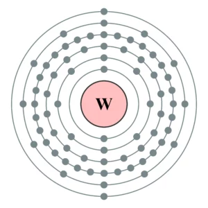
Electron shell 074 Tungsten no label 300x300 1

Tungsten is a very hard and heaviest metal. It is the rarest element found naturally. Let us focus on the electrical conductivity of tungsten. The electrical conductivity of the tungsten depends on the temperature. Tungsten can conduct electricity at high temperatures. In normal conditions, tungsten does not offer any electrical conductivity because of its resistive … Read more

Does Graphite Conduct Electricity?

does graphite conduct electricity

Graphite is a form of carbon that is known for its ability to conduct electricity. This is due to the presence of free electrons in its structure, which can move and carry electric charge. The electrical conductivity of graphite is influenced by several factors, including its crystalline structure, the presence of impurities, and the temperature … Read more

Does Salt Water Conduct Electricity?

does salt water conduct electricity

Salt water is a highly conductive medium due to the presence of dissolved ions, making it an excellent conductor of electricity. This property has numerous applications in various fields, from electrochemistry to marine engineering. In this comprehensive guide, we will delve into the science behind the conductivity of salt water, explore the factors that influence … Read more

Magnetic Field Lines Around a Magnet: A Comprehensive Guide

magnetic field lines around a magnet

Magnetic field lines around a magnet are a powerful tool for visualizing and understanding the behavior of magnetic fields. These invisible lines of force not only provide a qualitative representation of the field but also offer valuable insights into the quantitative aspects of magnetic phenomena. In this comprehensive guide, we will delve into the intricacies … Read more

Can Distance be a Curve?

can distance be a curve

In the realm of physics, the concept of distance being a curve is a fundamental aspect of non-Euclidean geometries, differential geometry, and general relativity. This intriguing idea challenges the traditional notion of distance as a straight line and opens up a world of fascinating mathematical and physical insights.

Understanding Curved Distances

The notion of distance as a curve arises from the study of non-Euclidean geometries, where the traditional Euclidean axioms of parallel lines and the sum of angles in a triangle being 180 degrees do not hold true. In these non-Euclidean spaces, the distance between two points is not necessarily represented by a straight line, but rather by a curve that minimizes the length between them.

One of the key concepts in this context is the geodesic, which is the shortest path between two points in a curved space. In the realm of general relativity, the path of a particle moving under the influence of gravity is a geodesic in spacetime. The length of a geodesic can be calculated using the metric tensor, which describes the geometry of spacetime.

Another important concept is the metric space, where the distance between two points is defined as the length of the shortest path between them, which can be a curve. The length of a curve in a metric space can be calculated using the integral of the norm of its velocity vector with respect to time.

Technical Specifications
can distance be a curve

Differential Geometry

In differential geometry, the length of a curve is given by the integral of the square root of the dot product of the derivative of the position vector with respect to time and itself. Mathematically, this can be expressed as:

$L = \int_{t_1}^{t_2} \sqrt{\dot{\mathbf{r}}(t) \cdot \dot{\mathbf{r}}(t)} dt$

where $\mathbf{r}(t)$ is the position vector of the curve as a function of time.

General Relativity

In the context of general relativity, the length of a curve in spacetime is given by the integral of the line element, which is a function of the metric tensor and the coordinates of the curve. The line element is expressed as:

$ds^2 = g_{\mu\nu} dx^\mu dx^\nu$

where $g_{\mu\nu}$ is the metric tensor and $dx^\mu$ are the differentials of the coordinates.

Metric Space

In a metric space, the distance between two points $x$ and $y$ is defined as the infimum of the set of lengths of all curves connecting them. Mathematically, this is expressed as:

$d(x, y) = \inf { L(\gamma) : \gamma \text{ is a curve connecting } x \text{ and } y }$

where $L(\gamma)$ is the length of the curve $\gamma$.

Theorems and Formulas

  1. Curve Length in Differential Geometry: The length of a curve in differential geometry is given by the formula:
    $L = \int_{t_1}^{t_2} \sqrt{\dot{\mathbf{r}}(t) \cdot \dot{\mathbf{r}}(t)} dt$

  2. Line Element in General Relativity: The line element in general relativity is given by the formula:
    $ds^2 = g_{\mu\nu} dx^\mu dx^\nu$

  3. Distance in Metric Space: The distance between two points $x$ and $y$ in a metric space is defined as:
    $d(x, y) = \inf { L(\gamma) : \gamma \text{ is a curve connecting } x \text{ and } y }$

Examples and Numerical Problems

Example: Curve Length Calculation

Calculate the length of the curve given by the parametric equations:
$x(t) = t^2$, $y(t) = t^3$, and $z(t) = \sin(t)$ from $t = 0$ to $t = 1$.

Numerical Problem: Curve Fitting and Length Calculation

Given a set of data points in $\mathbb{R}^3$, find the curve of best fit and calculate its length.

Figures and Data Points

Figure: Curve in $\mathbb{R}^3$

Curve in 3D Space
A curve in $\mathbb{R}^3$ with its length marked.

Data Points: Object Position

Time (s) X (m) Y (m) Z (m)
0 0 0 0
1 1 2 1
2 4 6 2
3 9 12 3
4 16 20 4

A set of data points in $\mathbb{R}^3$ representing the position of an object at different times.

Values and Measurements

  • Value: The length of a curve can be measured in units of length, such as meters or feet.
  • Measurement: The length of a curve can be measured using various techniques, such as numerical integration or approximating the curve with straight line segments.

Reference Links

  1. Differential Geometry
  2. General Relativity
  3. Metric Space

Magnetic Field Between Two Parallel Wires: A Comprehensive Guide

magnetic field between two parallel wires

Summary

The magnetic field between two parallel wires is a fundamental concept in electromagnetism, with numerous applications in various fields of physics and engineering. This comprehensive guide will delve into the detailed analysis of the magnetic field and the associated forces between two parallel current-carrying wires, providing a thorough understanding of the underlying principles and practical applications.

Understanding the Magnetic Field Between Parallel Wires

magnetic field between two parallel wires

The magnetic field between two parallel wires can be calculated using the formula:

B = μ0 * I / (2 * π * d)

where:
B is the magnetic field strength (in Tesla, T)
μ0 is the permeability of free space (4π × 10^-7 T⋅m/A)
I is the current flowing through the wires (in Amperes, A)
d is the distance between the two parallel wires (in meters, m)

This formula is derived from the Biot-Savart law, which describes the magnetic field generated by a current-carrying wire.

Factors Affecting the Magnetic Field

The magnetic field between two parallel wires is influenced by several key factors:

  1. Current Magnitude: The strength of the magnetic field is directly proportional to the current flowing through the wires. Doubling the current will result in a doubling of the magnetic field.

  2. Distance Between Wires: The magnetic field decreases inversely with the distance between the wires. Doubling the distance between the wires will result in a halving of the magnetic field.

  3. Permeability of the Medium: The magnetic field is also affected by the permeability of the medium surrounding the wires. In this case, the formula assumes the wires are in a vacuum or air, where the permeability is that of free space (μ0).

Practical Example

Let’s consider a practical example to illustrate the calculation of the magnetic field between two parallel wires.

Suppose we have two parallel wires carrying a current of 10 Amperes (A) and the distance between them is 2 centimeters (cm) or 0.02 meters (m).

Using the formula:

B = μ0 * I / (2 * π * d)
B = (4π × 10^-7 T⋅m/A) × (10 A) / (2 × π × 0.02 m)
B = 0.01 Tesla (T)

Therefore, the magnetic field between the two parallel wires is 0.01 Tesla (T).

Magnetic Force Between Parallel Wires

In addition to the magnetic field, the interaction between the two parallel wires also results in a magnetic force. This force can be calculated using the formula:

F = μ0 * I1 * I2 / (2 * π * d)

where:
F is the magnetic force between the wires (in Newtons, N)
I1 and I2 are the currents flowing through the respective wires (in Amperes, A)
d is the distance between the two parallel wires (in meters, m)

Attractive and Repulsive Forces

The direction of the magnetic force between the parallel wires depends on the relative direction of the currents:

  1. Attractive Force: If the currents in the two wires are in the same direction, the magnetic force between them will be attractive.
  2. Repulsive Force: If the currents in the two wires are in opposite directions, the magnetic force between them will be repulsive.

Practical Example

Let’s consider the same example as before, where we have two parallel wires carrying a current of 10 Amperes (A) and the distance between them is 2 centimeters (cm) or 0.02 meters (m).

Using the formula:

F = μ0 * I1 * I2 / (2 * π * d)
F = (4π × 10^-7 T⋅m/A) × (10 A) × (10 A) / (2 × π × 0.02 m)
F = 0.002 Newtons (N)

Therefore, the magnetic force between the two parallel wires is 0.002 Newtons (N), and the direction of the force will depend on the relative direction of the currents in the wires.

Practical Applications and Considerations

The understanding of the magnetic field and force between parallel wires has numerous practical applications in various fields, including:

  1. Electrical Circuits: The magnetic field and force between parallel wires are crucial in the design and analysis of electrical circuits, particularly in the context of transformers, motors, and generators.

  2. Electromagnetic Devices: The principles of magnetic field and force between parallel wires are fundamental to the operation of various electromagnetic devices, such as solenoids, relays, and electromagnetic actuators.

  3. Particle Accelerators: In particle accelerators, such as cyclotrons and synchrotrons, the magnetic field between parallel wires is used to guide and control the motion of charged particles.

  4. Magnetic Levitation: The repulsive magnetic force between parallel wires can be utilized in magnetic levitation systems, where objects are suspended in the air without physical contact.

  5. Magnetic Shielding: The magnetic field between parallel wires can be used to create magnetic shielding, which is important in protecting sensitive electronic equipment from external magnetic interference.

When working with magnetic fields and forces between parallel wires, it is essential to consider factors such as the material properties of the wires, the presence of ferromagnetic materials, and the potential for electromagnetic interference with other nearby systems.

Conclusion

The magnetic field and force between two parallel wires are fundamental concepts in electromagnetism with a wide range of practical applications. By understanding the underlying principles, formulas, and the factors that influence these phenomena, physicists, engineers, and researchers can effectively design, analyze, and optimize various electromagnetic systems and devices. This comprehensive guide provides a detailed exploration of the topic, equipping readers with the necessary knowledge and tools to navigate the complexities of magnetic field interactions between parallel wires.

Reference:

  1. Magnetic Force between Two Parallel Conductors
  2. Attraction between two wires with parallel current
  3. Calculating Magnetic Field Between Parallel Wires
  4. Magnetic Force Between Two Parallel Current Carrying Wires
  5. Magnetic Force between Two Parallel Currents

Magnetic Field and Current: A Comprehensive Guide for Physics Students

magnetic field and current

Magnetic fields are fundamental to our understanding of electromagnetism and play a crucial role in various applications, from power generation to medical imaging. This comprehensive guide delves into the intricate relationship between magnetic fields and electric currents, providing physics students with a detailed exploration of the underlying principles, formulas, and practical applications.

Understanding Magnetic Fields

Magnetic fields are invisible regions of space where magnetic forces can be detected. These fields are generated by moving electric charges, such as in a current-carrying wire, or by the intrinsic magnetic properties of certain materials, like permanent magnets.

The strength of a magnetic field is typically measured in units of Tesla (T) or Gauss (G), where 1 T is equivalent to 10,000 G. The magnetic field strength is a measure of the intensity of the magnetic force experienced by a charged particle moving within the field.

Ampere’s Law and Magnetic Field Calculations

The relationship between electric current and the resulting magnetic field is described by Ampere’s Law. This fundamental principle states that the magnetic field around a closed loop is proportional to the current flowing through the loop. Specifically, the magnetic field B at a distance r from a long, straight wire carrying a current I is given by:

B = μ₀I / (2πr)

where μ₀ is the permeability of free space, with a value of 4π x 10^-7 T m/A.

For a coil of wire with N turns, the magnetic field at the center of the coil is given by:

B = μ₀NI / L

where L is the length of the coil.

Magnetic Field Direction and the Right-Hand Rule

The direction of the magnetic field produced by a current-carrying wire is determined by the right-hand rule. If the thumb of the right hand is pointed in the direction of the current, the fingers will curl in the direction of the magnetic field.

Permanent Magnets and Magnetic Field Measurement

magnetic field and current

In addition to being produced by electric currents, magnetic fields can also be generated by permanent magnets. The strength of the magnetic field produced by a magnet depends on the material and shape of the magnet, as well as the distance from the magnet.

The magnetic field strength of a magnet can be measured using various instruments, such as a Hall probe or a fluxgate magnetometer. These devices can provide precise measurements of the magnetic field in a specific location, allowing for the characterization of magnetic field patterns and the identification of magnetic field anomalies.

Applications of Magnetic Fields and Current

The relationship between magnetic fields and electric currents is fundamental to many applications in physics and engineering, including:

Electromagnets

In an electromagnet, increasing the current flowing through the coil will increase the magnetic field produced, which can be used to attract or repel magnetic objects. This principle is utilized in a wide range of devices, from electric motors and generators to magnetic resonance imaging (MRI) machines.

Generators

In a generator, the magnetic field produced by a rotating magnet is used to induce a current in a nearby coil. This induced current can then be used to power electrical devices, making generators an essential component of power generation systems.

Motors

In a motor, a current-carrying coil is placed in a magnetic field, causing the coil to experience a force that causes it to rotate. This rotational force can be used to drive mechanical devices, such as fans, pumps, and compressors.

Transformers

Transformers rely on the relationship between magnetic fields and electric currents to transfer electrical energy between two or more circuits. By using a changing magnetic field, transformers can step up or step down the voltage of an alternating current (AC) signal, enabling efficient power transmission and distribution.

Numerical Examples and Problem-Solving

To further solidify your understanding of magnetic fields and their relationship with electric currents, let’s explore some numerical examples and problem-solving exercises.

Example 1: Calculating Magnetic Field from a Current-Carrying Wire

Suppose a long, straight wire is carrying a current of 10 A. Calculate the magnetic field strength at a distance of 5 cm from the wire.

Given:
– Current, I = 10 A
– Distance from the wire, r = 5 cm = 0.05 m
– Permeability of free space, μ₀ = 4π × 10^-7 T⋅m/A

Using the formula for the magnetic field around a current-carrying wire:

B = μ₀I / (2πr)
B = (4π × 10^-7 T⋅m/A) × (10 A) / (2π × 0.05 m)
B = 2 × 10^-5 T = 0.2 G

Therefore, the magnetic field strength at a distance of 5 cm from the wire is 0.2 G.

Example 2: Calculating Magnetic Field in a Coil

A coil of wire has 100 turns and carries a current of 5 A. If the length of the coil is 20 cm, calculate the magnetic field at the center of the coil.

Given:
– Number of turns, N = 100
– Current, I = 5 A
– Length of the coil, L = 20 cm = 0.2 m
– Permeability of free space, μ₀ = 4π × 10^-7 T⋅m/A

Using the formula for the magnetic field at the center of a coil:

B = μ₀NI / L
B = (4π × 10^-7 T⋅m/A) × (100) × (5 A) / (0.2 m)
B = 0.0157 T = 157 G

Therefore, the magnetic field at the center of the coil is 157 G.

Problem-Solving Exercise

A circular coil with a radius of 10 cm carries a current of 2 A. Calculate the magnetic field at the center of the coil and the magnetic field at a distance of 5 cm from the center of the coil.

To solve this problem, you will need to use the formulas for the magnetic field at the center of a coil and the magnetic field around a current-carrying wire.

Remember to show your work and provide the final answers with the appropriate units.

Conclusion

Magnetic fields and their relationship with electric currents are fundamental concepts in physics, with numerous practical applications. By understanding the underlying principles, formulas, and problem-solving techniques, physics students can develop a comprehensive understanding of this crucial topic and apply it to a wide range of real-world scenarios.

References

  1. “Magnetic Fields and Distance – Activity” by TeachEngineering
  2. “Physics 232 (Lab 8) Measurements of magnetic field in a coil (analysis lab)” by Northern Virginia Community College
  3. “Magnetic Field Strength” by ScienceDirect Topics
  4. “Current to Magnetic Field: Calculation, Formula & Direction” by Vaia
  5. “How Do You Measure the Magnetic Field?” by Wired
  6. “Effects of External Electrical and Magnetic Fields on Pacemakers and Defibrillators: From Engineering Principles to Clinical Practice” by Circulation, PubMed Central

Magnetic Flux in a Wire: A Comprehensive Guide

magnetic flux in a wire

Magnetic flux is a fundamental concept in electromagnetism, and understanding its behavior in a wire is crucial for various applications, such as electrical engineering, power generation, and magnetic field analysis. This comprehensive guide will delve into the technical details of magnetic flux in a wire, providing you with a thorough understanding of the topic.

Understanding Magnetic Flux

Magnetic flux, denoted by the Greek letter Φ, is a measure of the total magnetic field that passes through a given surface area. It is expressed in the SI unit of weber (Wb) or tesla-meter squared (Tm²). Magnetic flux is a vector quantity, meaning it has both magnitude and direction.

The magnetic flux through a surface area A perpendicular to the magnetic field B can be calculated using the formula:

Φ = B × A × cos(θ)

where θ is the angle between the magnetic field and the normal to the surface area.

Magnetic Field around a Current-Carrying Wire

magnetic flux in a wire

When a current I flows through a wire, it generates a magnetic field around the wire. This magnetic field can be calculated using Ampere’s law, which states that the line integral of the magnetic field around a closed loop is proportional to the current enclosed by the loop.

For a long, straight wire carrying a current I, the magnetic field B at a distance r from the wire is given by:

B = (μ₀ × I) / (2π × r)

where μ₀ is the permeability of free space, which has a value of approximately 4π × 10⁻⁷ Tm/A.

Calculating Magnetic Flux in a Wire

To calculate the magnetic flux through a surface area A perpendicular to the magnetic field generated by a current-carrying wire, we can use the formula:

Φ = B × A × cos(θ)

where θ is the angle between the magnetic field and the normal to the surface area.

Let’s consider an example:
* Wire carrying a current of 2 A
* Surface area of 0.5 m²
* Distance from the wire: 0.1 m

The magnetic field at a distance of 0.1 m from the wire can be calculated as:

B = (μ₀ × I) / (2π × r)
B = (4π × 10⁻⁷ Tm/A × 2 A) / (2π × 0.1 m)
B = 4 × 10⁻⁵ T

Assuming the surface area is perpendicular to the magnetic field (θ = 0°), the magnetic flux can be calculated as:

Φ = B × A × cos(θ)
Φ = (4 × 10⁻⁵ T) × (0.5 m²) × 1
Φ = 2 × 10⁻⁵ Wb

Therefore, the magnetic flux through the surface area is 2 × 10⁻⁵ webers.

Factors Affecting Magnetic Flux in a Wire

Several factors can influence the magnetic flux in a wire, including:

  1. Current Magnitude: The strength of the magnetic field, and consequently the magnetic flux, is directly proportional to the current flowing through the wire.

  2. Distance from the Wire: As the distance from the wire increases, the magnetic field and magnetic flux decrease according to the inverse square law.

  3. Angle between the Magnetic Field and the Surface Area: The magnetic flux is maximized when the surface area is perpendicular to the magnetic field (θ = 0°) and decreases as the angle increases.

  4. Wire Geometry: The shape and configuration of the wire can affect the distribution and strength of the magnetic field, which in turn influences the magnetic flux.

  5. Magnetic Properties of the Material: The permeability of the material surrounding the wire can also impact the magnetic flux, as it affects the magnetic field lines.

Measuring Magnetic Flux in a Wire

Magnetic flux in a wire can be measured using various instruments, such as:

  1. Magnetometer: A magnetometer is a device that measures the strength and direction of the magnetic field. By placing a magnetometer near the wire, you can determine the magnetic flux density and calculate the total magnetic flux.

  2. Flux Meter: A flux meter is a specialized instrument designed to directly measure the magnetic flux. It typically consists of a search coil that is placed in the magnetic field, and the induced voltage is used to calculate the flux.

  3. Hall Effect Sensor: Hall effect sensors can be used to measure the magnetic field strength, which can then be used to calculate the magnetic flux.

  4. Faraday’s Law of Electromagnetic Induction: By measuring the induced voltage in a loop of wire placed in the magnetic field, you can calculate the magnetic flux using Faraday’s law.

Applications of Magnetic Flux in Wires

Magnetic flux in wires is crucial for various applications, including:

  1. Electrical Transformers: Transformers rely on the magnetic flux generated by the primary winding to induce a voltage in the secondary winding, enabling the transformation of voltage levels.

  2. Electric Motors and Generators: The interaction between the magnetic flux and the current-carrying conductors in motors and generators is the fundamental principle behind their operation.

  3. Magnetic Resonance Imaging (MRI): MRI machines use strong magnetic fields and magnetic flux to generate detailed images of the human body for medical diagnosis and research.

  4. Magnetic Field Sensing: Magnetic flux measurements are used in various applications, such as position sensing, current sensing, and magnetic field mapping.

  5. Electromagnetic Induction: The changing magnetic flux in a wire can induce a voltage in another wire, which is the basis for many electromagnetic induction phenomena, such as in transformers and generators.

Conclusion

Magnetic flux in a wire is a crucial concept in electromagnetism, with numerous applications in various fields. By understanding the principles, formulas, and factors affecting magnetic flux, you can effectively analyze and manipulate the magnetic fields in wires to achieve desired outcomes. This comprehensive guide has provided you with the necessary knowledge and tools to delve deeper into the world of magnetic flux in wires.

References

  1. “Magnetic Flux” by BYJU’S, available at: https://byjus.com/physics/magnetic-flux/
  2. “How to Calculate the Flux Perpendicular to a Loop of Wire” by Study.com, available at: https://study.com/skill/learn/how-to-calculate-the-flux-perpendicular-to-a-loop-of-wire-explanation.html
  3. “The Magnetic Field due to a Current in a Straight Wire” by Nagwa, available at: https://www.nagwa.com/en/explainers/909137183476/
  4. “Magnetic flux density measured for beginners: from fizzics.org” by The Engineering Mindset, available at: https://www.youtube.com/watch?v=3nGc44rYXww