How To Calculate Flux Linkage: Detailed Insight And Facts

Flux linkage is an important concept in electromagnetism that helps us understand the relationship between magnetic fields and circuits. It quantifies the amount of magnetic flux that passes through a given coil or circuit. In this blog post, we will explore how to calculate flux linkage in detail, providing step-by-step instructions, formulas, and examples to ensure a thorough understanding.

The Mathematical Approach to Flux Linkage
Flux Linkage Formula

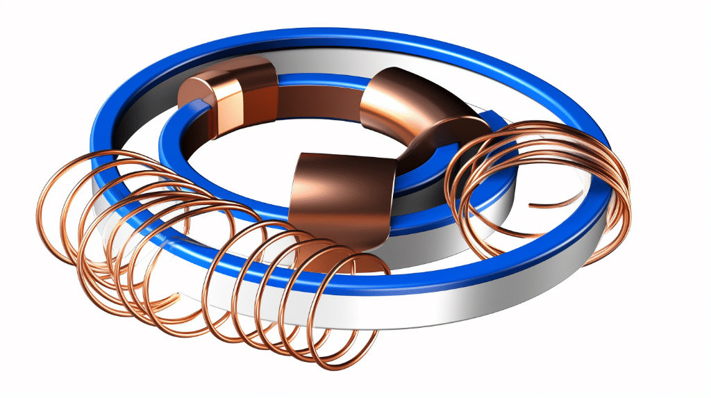
Before diving into the calculations, let’s understand the basic formula for flux linkage. Flux linkage ((\lambda)) is defined as the product of the number of turns in a coil ((N)) and the magnetic flux ((\Phi)) passing through it. Mathematically, it can be expressed as:

[ \lambda = N \cdot \Phi ]\tag{1}

where:
(\lambda) represents the flux linkage,
(N) is the number of turns in the coil, and
(\Phi) denotes the magnetic flux passing through the coil.

Total Flux Linkage Formula

In some cases, a circuit may have multiple coils or loops. To calculate the total flux linkage in such a scenario, we need to sum up the individual flux linkages for each coil. The total flux linkage ((\Lambda)) is given by:

[ \Lambda = \sum \lambda_i ]\tag{2}

where:
(\Lambda) represents the total flux linkage, and
(\lambda_i) is the flux linkage for the (i)-th coil.

How to Calculate Flux Linkage

Now that we understand the formulas, let’s go through a step-by-step guide to calculate flux linkage.

Step-by-step Guide to Calculate Magnetic Field Flux Linkage

Step 1: Determine the number of turns ((N)) in the coil.
Step 2: Measure the magnetic flux ((\Phi)) passing through the coil.
Step 3: Use the formula (\lambda = N \cdot \Phi) to calculate the flux linkage.

Let’s work through an example to solidify our understanding.

Example 1:
Suppose we have a coil with 100 turns, and the magnetic flux passing through it is 0.05 Weber. To calculate the flux linkage, we can use the formula (\lambda = N \cdot \Phi):

[ \lambda = 100 \cdot 0.05 = 5 \text{ Weber-turns} ]

Therefore, the flux linkage for this coil is 5 Weber-turns.

How to Calculate Change in Magnetic Flux Linkage
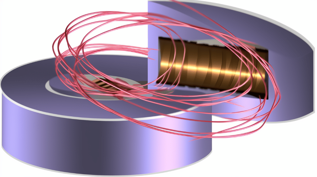
In certain situations, the magnetic flux passing through a coil may change. To calculate the change in magnetic flux linkage, we can use the formula:

[ \Delta \lambda = N \cdot \Delta \Phi ]\tag{3}

where:
(\Delta \lambda) represents the change in flux linkage,
(N) is the number of turns in the coil, and
(\Delta \Phi) denotes the change in magnetic flux passing through the coil.

Worked-out Examples on Flux Linkage Calculation

Let’s work through a couple of examples to further solidify our understanding.

Example 2:
Consider a coil with 50 turns. The magnetic flux passing through the coil changes from 0.02 Weber to 0.05 Weber. To calculate the change in flux linkage, we can use the formula (\Delta \lambda = N \cdot \Delta \Phi):

[ \Delta \lambda = 50 \cdot (0.05 - 0.02) = 1.5 \text{ Weber-turns} ]

Therefore, the change in flux linkage for this coil is 1.5 Weber-turns.

Example 3:
Let’s consider a scenario where a coil has 200 turns, and the magnetic flux passing through it remains constant at 0.1 Weber. In this case, since there is no change in magnetic flux, the change in flux linkage ((\Delta \lambda)) would be zero.

Advanced Concepts in Flux Linkage

How to Determine Maximum Flux Linkage

To determine the maximum flux linkage ((\lambda_{\text{max}})) in a coil, we need to consider the maximum value of magnetic flux ((\Phi_{\text{max}})) passing through the coil. We can use the formula (\lambda_{\text{max}} = N \cdot \Phi_{\text{max}}) to calculate it.

Practical Applications of Flux Linkage Calculations

Flux linkage calculations have various practical applications. They are extensively used in the design and analysis of electrical transformers, electric motors, and generators. Understanding flux linkage is crucial for optimizing the performance and efficiency of these devices.

What is the difference between magnetic flux and magnetic flux linkage?

The difference between magnetic flux and magnetic flux linkage lies in their definitions and applications. Magnetic flux refers to the total magnetic field passing through a surface, while magnetic flux linkage refers to the product of magnetic flux and the number of turns in a coil. To learn more about the distinction between these two concepts, you can visit the article on Difference between magnetic flux and magnetic flux linkage.

Numerical Problems on How to Calculate Flux Linkage

Problem 1:

A coil with 100 turns is wound around a magnetic core. The core has a magnetic field strength of 0.05 T and an area of 0.02 m². Calculate the flux linkage in the coil.

Solution:
To calculate the flux linkage, we can use the formula:

 \text{Flux Linkage} = \text{Number of Turns} \times \text{Magnetic Flux}

The magnetic flux can be calculated using the formula:

 \text{Magnetic Flux} = \text{Magnetic Field Strength} \times \text{Area}

Substituting the given values into the formulas, we get:

 \text{Magnetic Flux} = 0.05 \, \text{T} \times 0.02 \, \text{m}^2 = 0.001 \, \text{Wb}

 \text{Flux Linkage} = 100 \, \text{turns} \times 0.001 \, \text{Wb} = 0.1 \, \text{Wb}

Therefore, the flux linkage in the coil is 0.1 Wb.

Problem 2:

how to calculate flux linkage
Image by Nicholas D. Ward, Thomas S. Bianchi, Patricia M. Medeiros, Michael Seidel, Jeffrey E. Richey, Richard G. Keil and Henrique O. Sawakuchi – Wikimedia Commons, Licensed under CC BY-SA 4.0.

A solenoid has 500 turns and a magnetic field strength of 0.02 T. The length of the solenoid is 0.1 m. Calculate the flux linkage in the solenoid.

Solution:
To calculate the flux linkage, we can use the formula:

 \text{Flux Linkage} = \text{Number of Turns} \times \text{Magnetic Flux}

The magnetic flux can be calculated using the formula:

 \text{Magnetic Flux} = \text{Magnetic Field Strength} \times \text{Area} \times \text{Number of Turns}

The area of the solenoid can be calculated using the formula:

 \text{Area} = \text{Length of Solenoid} \times \text{Turns per Unit Length}

Substituting the given values into the formulas, we get:

 \text{Area} = 0.1 \, \text{m} \times \frac{500}{0.1 \, \text{m}} = 5 \, \text{m}^2

 \text{Magnetic Flux} = 0.02 \, \text{T} \times 5 \, \text{m}^2 \times 500 = 10 \, \text{Wb}

 \text{Flux Linkage} = 500 \, \text{turns} \times 10 \, \text{Wb} = 5000 \, \text{Wb}

Therefore, the flux linkage in the solenoid is 5000 Wb.

Problem 3:
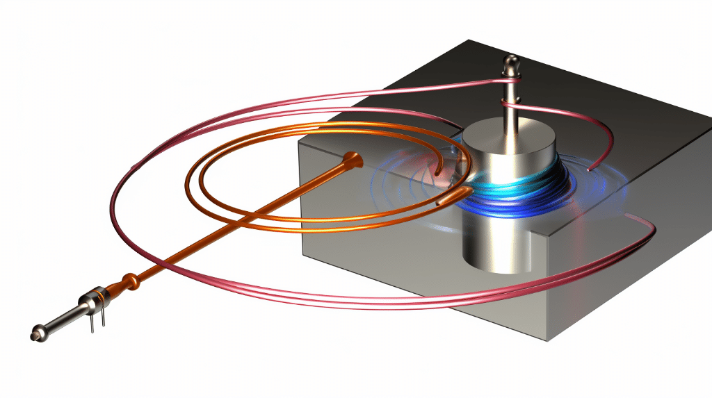
A circular coil with a radius of 0.1 m is placed in a magnetic field with a magnetic flux density of 0.04 T. The coil has 200 turns. Calculate the flux linkage in the coil.

Solution:
To calculate the flux linkage, we can use the formula:

 \text{Flux Linkage} = \text{Number of Turns} \times \text{Magnetic Flux}

The magnetic flux can be calculated using the formula:

 \text{Magnetic Flux} = \text{Magnetic Flux Density} \times \text{Area}

The area of the circular coil can be calculated using the formula:

 \text{Area} = \pi \times \text{Radius}^2

Substituting the given values into the formulas, we get:

 \text{Area} = \pi \times (0.1 \, \text{m})^2 = 0.0314 \, \text{m}^2

 \text{Magnetic Flux} = 0.04 \, \text{T} \times 0.0314 \, \text{m}^2 = 0.00126 \, \text{Wb}

 \text{Flux Linkage} = 200 \, \text{turns} \times 0.00126 \, \text{Wb} = 0.252 \, \text{Wb}

Therefore, the flux linkage in the coil is 0.252 Wb.

Also Read:

Faraday’s Law of Induction, Lenz’s Law, and Magnetic Flux: A Comprehensive Guide

faradays law of induction lenzs law

Faraday’s Law of Induction and Lenz’s Law are fundamental principles in electromagnetism that describe the relationship between changing magnetic fields and the induced electromotive forces (EMFs) they create. These laws are essential for understanding the behavior of various electromagnetic devices, from transformers and generators to induction motors and wireless charging systems. In this comprehensive guide, we will delve into the mathematical formulations, key concepts, practical applications, and numerical examples related to these important laws.

Faraday’s Law of Induction

Faraday’s Law of Induction states that the induced EMF in a circuit is proportional to the rate of change of the magnetic flux through the circuit. The mathematical expression for Faraday’s Law is:

[
\text{emf} = -N \frac{\Delta \Phi}{\Delta t}
]

Where:
emf: Electromotive force (volts, V)
N: Number of turns in the coil
ΔΦ: Change in magnetic flux (weber, Wb)
Δt: Time over which the flux changes (seconds, s)

The negative sign in the equation indicates that the induced EMF opposes the change in magnetic flux, as described by Lenz’s Law.

Magnetic Flux

Magnetic flux, denoted as Φ, is a measure of the total magnetic field passing through a given surface or area. The formula for magnetic flux is:

[
\Phi = B \cdot A \cdot \cos \theta
]

Where:
Φ: Magnetic flux (weber, Wb)
B: Magnetic field strength (tesla, T)
A: Area of the coil (square meters, m²)
θ: Angle between the magnetic field and the coil normal (degrees)

The magnetic flux is directly proportional to the magnetic field strength, the area of the coil, and the cosine of the angle between the magnetic field and the coil normal.

Lenz’s Law

faradays law of induction lenzs law flux

Lenz’s Law states that the direction of the induced current in a circuit is such that it opposes the change in the magnetic flux that caused it. In other words, the induced current will create a magnetic field that opposes the original change in the magnetic field.

To determine the direction of the induced current, you can use the right-hand rule:
1. Point your thumb in the direction of the magnetic field.
2. Curl your fingers around the coil or circuit.
3. The direction your fingers curl is the direction of the induced current.

This rule helps you visualize the direction of the induced current and ensures that it opposes the change in the magnetic flux, as described by Lenz’s Law.

Examples and Applications

Induction Cooker

  • Magnetic Field Strength: Typically around 100 mT (millitesla)
  • Frequency: 27 kHz (kilohertz)
  • Induced EMF: High values due to the high rate of change of the magnetic field

Induction cookers use the principles of electromagnetic induction to heat cookware. The rapidly changing magnetic field induces a high EMF in the metal cookware, which in turn generates heat through eddy currents.

Transformer

  • Mutual Inductance: The ability of two coils to induce EMFs in each other
  • Efficiency: Transformers can achieve high efficiency (up to 99%) due to the principles of electromagnetic induction

Transformers rely on the mutual inductance between two coils to step up or step down the voltage in an electrical system. The changing magnetic field in the primary coil induces a corresponding EMF in the secondary coil, allowing for efficient power transformation.

Electric Generator

  • EMF: Varies sinusoidally with time
  • Angular Velocity: The coil is rotated at a constant angular velocity to produce the EMF

Electric generators convert mechanical energy into electrical energy by using the principles of electromagnetic induction. As a coil is rotated in a magnetic field, the changing magnetic flux induces an EMF that varies sinusoidally with time.

Numerical Problems

Example 1

  • Change in Flux: 2 Wb to 0.2 Wb in 0.5 seconds
  • Induced EMF: Calculate the induced EMF using Faraday’s Law

Solution:
[
\Delta \Phi = 0.2 – 2 = -1.8 \text{ Wb}
]
[
\text{emf} = -N \frac{\Delta \Phi}{\Delta t} = -N \frac{-1.8}{0.5} = 3.6 N \text{ V}
]

Example 2

  • Coil Area: 0.1 m²
  • Magnetic Field Strength: 0.5 T
  • Angle: 30°
  • Number of Turns: 100
  • Time: 0.2 seconds
  • Change in Flux: Calculate the change in flux and the induced EMF

Solution:
[
\Phi = B \cdot A \cdot \cos \theta = 0.5 \cdot 0.1 \cdot \cos 30° = 0.043 \text{ Wb}
]
[
\Delta \Phi = 0.043 \text{ Wb}
]
[
\text{emf} = -N \frac{\Delta \Phi}{\Delta t} = -100 \frac{0.043}{0.2} = -21.5 \text{ V}
]

References

  1. Lumen Learning. (n.d.). Faraday’s Law of Induction: Lenz’s Law. Retrieved from https://courses.lumenlearning.com/suny-physics/chapter/23-2-faradays-law-of-induction-lenzs-law/
  2. Boundless Physics. (n.d.). Magnetic Flux, Induction, and Faraday’s Law. Retrieved from https://www.collegesidekick.com/study-guides/boundless-physics/magnetic-flux-induction-and-faradays-law
  3. ScienceDirect. (n.d.). Faraday’s Law. Retrieved from https://www.sciencedirect.com/topics/physics-and-astronomy/faradays-law
  4. GeeksforGeeks. (2022). Faraday’s Law of Electromagnetic Induction: Experiment & Formula. Retrieved from https://www.geeksforgeeks.org/faradays-law/
  5. Science in School. (2021). Faraday’s law of induction: from classroom to kitchen. Retrieved from https://www.scienceinschool.org/article/2021/faradays-law-induction-classroom-kitchen/