Magnetic Field at the Center of a Current Loop: A Comprehensive Guide

magnetic field at center of loop

The magnetic field at the center of a circular loop carrying a current is a fundamental concept in electromagnetism, with numerous applications in various fields of physics and engineering. This comprehensive guide will delve into the theoretical underpinnings, practical considerations, and measurement techniques related to this topic, providing a valuable resource for physics students and enthusiasts.

Understanding the Theoretical Foundations

Ampere’s Law and the Biot-Savart Law

The magnetic field at the center of a current loop can be derived using two fundamental laws of electromagnetism: Ampere’s Law and the Biot-Savart Law.

Ampere’s Law states that the line integral of the magnetic field around a closed path is proportional to the electric current enclosed by that path. Mathematically, this can be expressed as:

∮B⋅dl = μ0I

where B is the magnetic field, dl is an infinitesimal length element of the closed path, μ0 is the permeability of free space, and I is the electric current enclosed by the path.

The Biot-Savart Law, on the other hand, describes the magnetic field generated by an element of current. It states that the magnetic field dB at a point due to an infinitesimal current element I dl is given by:

dB = (μ0 / 4π) * (I dl × r) / r^2

where r is the vector from the current element to the point of interest.

By applying these laws to a circular current loop, one can derive the formula for the magnetic field at the center of the loop.

Derivation of the Magnetic Field Formula

Consider a circular loop of radius R carrying a current I. The magnetic field at the center of the loop can be calculated as follows:

  1. Divide the loop into infinitesimal current elements I dl.
  2. Apply the Biot-Savart Law to each current element to find the contribution to the magnetic field at the center.
  3. Integrate the contributions around the entire loop to obtain the total magnetic field.

The resulting formula for the magnetic field at the center of the loop is:

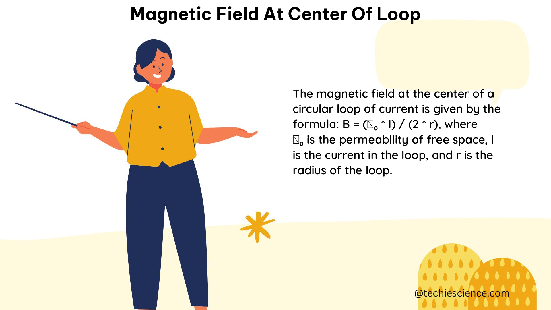
B = (μ0 * I) / (2 * R)

where μ0 is the permeability of free space, I is the current flowing through the loop, and R is the radius of the loop.

This formula provides an accurate representation of the magnetic field at the center of a circular current loop, assuming the loop is perfectly circular and the current is uniformly distributed around the loop.

Factors Affecting the Magnetic Field

While the formula B = (μ0 * I) / (2 * R) provides a good approximation of the magnetic field at the center of a current loop, there are several factors that can influence the actual magnetic field:

  1. Loop Geometry: The formula assumes a perfectly circular loop. Deviations from a circular shape, such as an elliptical or irregular loop, can affect the magnetic field distribution.
  2. Current Distribution: The formula assumes a uniform current distribution around the loop. In practice, the current may not be evenly distributed, leading to variations in the magnetic field.
  3. Proximity to Other Magnetic Fields: The presence of other magnetic fields, such as those generated by nearby current-carrying conductors or magnetic materials, can interact with the magnetic field of the current loop, altering the overall field.
  4. Temperature and Material Properties: The electrical and magnetic properties of the loop materials, such as the wire’s resistivity and the permeability of the loop, can change with temperature, affecting the magnetic field.

These factors should be considered when using the formula or when measuring the magnetic field at the center of a current loop.

Practical Considerations and Applications
magnetic field at center of loop

Numerical Examples

Let’s consider a few numerical examples to illustrate the application of the magnetic field formula:

  1. Example 1: A circular loop with a radius of 0.1 m carries a current of 2 A. Calculate the magnetic field at the center of the loop.

B = (μ0 * I) / (2 * R)
B = (4π × 10^-7 T·m/A) × (2 A) / (2 × 0.1 m)
B = 0.04π T

  1. Example 2: A circular loop with a radius of 0.5 m carries a current of 5 A. Calculate the magnetic field at the center of the loop.

B = (μ0 * I) / (2 * R)
B = (4π × 10^-7 T·m/A) × (5 A) / (2 × 0.5 m)
B = 0.1π T

These examples demonstrate how the magnetic field at the center of a current loop can be calculated using the provided formula.

Practical Applications

The magnetic field at the center of a current loop has numerous practical applications in various fields, including:

  1. Magnetic Resonance Imaging (MRI): MRI systems use strong, uniform magnetic fields to align the magnetic moments of hydrogen protons in the human body. The magnetic field at the center of the MRI coils is a critical parameter in the design and operation of these systems.

  2. Electric Motors and Generators: The magnetic field at the center of the armature windings in electric motors and generators plays a crucial role in the conversion of electrical energy to mechanical energy and vice versa.

  3. Particle Accelerators: Circular particle accelerators, such as cyclotrons and synchrotrons, rely on the magnetic field at the center of their circular paths to guide and accelerate charged particles.

  4. Magnetic Levitation: Maglev trains use the magnetic field at the center of their guideway coils to levitate the train, reducing friction and enabling high-speed transportation.

  5. Magnetic Sensors: Devices like Hall effect sensors and fluxgate magnetometers utilize the magnetic field at the center of their sensing elements to measure the strength and direction of magnetic fields.

These applications highlight the importance of understanding and accurately calculating the magnetic field at the center of a current loop.

Measurement Techniques and Instrumentation

Measuring the magnetic field at the center of a current loop requires specialized instrumentation and techniques. Some common methods and instruments used for this purpose include:

Hall Effect Sensors

Hall effect sensors are widely used to measure magnetic fields. They operate by detecting the voltage generated across a thin semiconductor material when a magnetic field is applied perpendicular to the material. Hall effect sensors can provide accurate and precise measurements of the magnetic field at the center of a current loop.

Fluxgate Magnetometers

Fluxgate magnetometers are another type of instrument used to measure magnetic fields. They consist of a ferromagnetic core wrapped with two coils: a primary coil that generates a magnetic field and a secondary coil that measures the changes in the magnetic field. Fluxgate magnetometers can provide high-sensitivity measurements of the magnetic field at the center of a current loop.

Search Coil Magnetometers

Search coil magnetometers, also known as induction magnetometers, measure the magnetic field by detecting the induced voltage in a coil of wire placed in the magnetic field. These instruments can be used to measure the magnetic field at the center of a current loop, particularly for time-varying or pulsed magnetic fields.

Calibration and Accuracy

Regardless of the measurement technique used, it is essential to calibrate the instruments to ensure accurate and reliable measurements of the magnetic field at the center of a current loop. Calibration can be performed using reference standards or by comparing the measurements with theoretical calculations.

The accuracy of the magnetic field measurements can be affected by various factors, such as the sensitivity and linearity of the instrument, the alignment of the sensor with the magnetic field, and the presence of external magnetic fields. It is important to consider these factors and take appropriate measures to minimize measurement errors.

Conclusion

The magnetic field at the center of a current loop is a fundamental concept in electromagnetism with numerous practical applications. By understanding the theoretical foundations, practical considerations, and measurement techniques related to this topic, physics students and enthusiasts can develop a comprehensive understanding of this important phenomenon.

This guide has provided a detailed exploration of the magnetic field at the center of a current loop, covering the derivation of the formula, the factors that can influence the magnetic field, practical applications, and measurement techniques. With this knowledge, readers can confidently apply the principles of electromagnetism to solve problems, design systems, and further their understanding of the physical world.

References:

  • Griffiths, D. J. (2013). Introduction to Electromagnetism (4th ed.). Pearson.
  • Serway, R. A., & Jewett, J. W. (2018). Physics for Scientists and Engineers with Modern Physics (10th ed.). Cengage Learning.
  • Halliday, D., Resnick, R., & Walker, J. (2013). Fundamentals of Physics (10th ed.). Wiley.
  • Nave, C. R. (n.d.). Magnetic Field of a Current Loop. HyperPhysics. http://hyperphysics.phy-astr.gsu.edu/hbase/magnetic/curloo.html
  • Magnetic Field Measurement Techniques. (n.d.). National High Magnetic Field Laboratory. https://nationalmaglab.org/education/magnet-academy/learn-the-basics/magnetic-field-measurement-techniques
The Comprehensive Guide to Center of Gravity 2: Mastering the Intricacies of Gravitational Systems

center of gravity 2

The concept of center of gravity (COG) is a fundamental principle in physics, particularly in the study of mechanics and gravitational systems. While the sources provided do not contain specific information about a “center of gravity 2” entity, this comprehensive guide will delve into the advanced aspects of COG, equipping you with a deep understanding … Read more

Center of Gravity 4: A Comprehensive Guide for Physics Students

center of gravity 4

The center of gravity (COG) is a fundamental concept in physics and engineering, representing the point where the weight of an object or system appears to act. For a 4-wheeled vehicle, the COG is a crucial parameter that determines its handling, stability, and performance characteristics. This comprehensive guide delves into the theoretical background, measurement techniques, … Read more

5+ Center Of Pressure Example: Detailed Facts

1 300x131 1

In this article the center of pressure example are going to be illustrated in a brief manner.

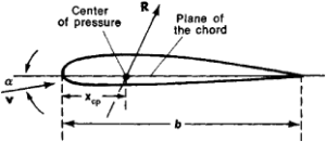
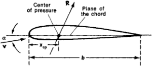
Before starting with the center of pressure example we should have the primary idea of center of pressure. Center of pressure is defined as the point where total pressure that acts on an object is concentrated, which in turn produces a force acting on that object. This force  in turn produces a moment of force that acts on that object.

Center of pressure example with their explanations are stated below:

Both static and dynamic fluid mechanics come under the application of the center of pressure. Usually the center of pressure is located inside the object but sometimes due to the effect of resultant force when a moment of force is generated the center of pressure can have a position outside the object.

The value of the center of pressure depends upon the inclined surface that is immersed in a liquid. Its value is also dependent upon the position of the centroid of an object too. By how much this liquid surface is immersed in a liquid the more the center of pressure is closer to the centroid.

But the weight of the liquid does not bother the center of pressure of that object.

center of pressure examplet
Center of pressure from wikipedia

Water dams

This is one important center of pressure example. Hydrostatic forces are those forces that depend on the depth of the liquid linearly. In water dams the force that acts is hydrostatic force. The total force that acts on the body is the product of total liquid pressure and the height of the dam.

The center of pressure of a triangular dam is positioned at the centroid of that dam from the ⅔ portion above the water surface. The moment of the force can be calculated from the position of the center of pressure and the value of the resultant force i.e, the hydrostatic force.

Sailboats

This is another notable center of pressure example. In a sailboat the center of pressure is that point where aerodynamic forces are concentrated. The aerodynamic center of pressure acting on the sails and the hydrodynamic center of pressure acting on the hull are related to each other in order to identify the direction of the boat with the flow of the wind.

2
Aerodynamic center from wikipedia

This behavior of the sailboat that is controlled by the direction of flow of the wind is known as helm. Helm is of two types. One is the weather helm and the other is the lee helm.

In the case of a weather helm, if the aerodynamic center of pressure is backward with the hydrodynamic center of pressure then the boat turns itself in the direction of the flow of the wind. If the aerodynamic center of pressure is in front to the hydrodynamic center of pressure then this condition will lead to the lee helm.

The weather helm is a desirable condition whereas the lee helm is an undesirable one. Too much of the helm is dangerous as it leads to extra drag beyond the minimal helm that a board experiences.

3
Lee helm from wikipedia

Aircrafts

We not only need a stable condition in case of sailing a boat but also in the aircraft. The center of pressure also plays a role in aircrafts. Not only a lift is produced in the non symmetrical aerofoil but also a moment of a force is generated in it.

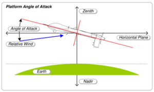
In case of aircrafts the center of pressure is defined as that point where all the aerodynamic pressure is concentrated and the force vector with zero moment acts. The aerodynamic center of an airfoil is that point where the moment is constant with respect to the angle of attack. This moment is produced by the aerodynamic forces.

This aerodynamic center plays an important role in the stability of all flying objects. When the angle of pitch and angle of attack get disturbed by the unwanted forces then the aircraft automatically comes back to its original angle of pitch without being controlled by the pilots by changing the control surface deflection.

A positive longitudinal static stability is needed by an aircraft to come back to its original angle of pitch without taking the help from the pilot.

Missiles

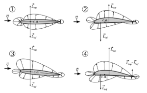
This is another important center of pressure example. Missiles consist of a number of symmetric airfoils. The center of pressure has a constant value for small angles of attack of the symmetric airfoils. In a missile basically a small change in the angle of attack creates additional pressure in the missiles. Hence the center of pressure of a missile is basically that point where there are additional pressure fields included also.

4
Angle of attack from wikipedia

Unguided missiles

In case of unguided rockets angle of attack is zero and the center of pressure provides the limit of angle of attack turning to zero. To obtain a positive stability in a missile the center of pressure should be stayed at a distance from the center of gravity of that missile.

The nose,wings and fins of a missile are used to control or manipulate the contributions of the center of pressure of the entire vehicle for a comparatively lower angle of attack. To calculate the position of the centroid that represents the center of pressure we should multiply the normal force coefficient with the position of the center of pressure.

The center of pressure of the additional pressure fields is positioned below the center of gravity of the missile. The additional force is directed in the same direction as the angle of attack of the missile. Now this force produces a moment which in turn help the missile to get back to its original position.

Guided missiles

In case of a guided missile the fins are used to change the position of the missile at various angles of attack. The center of pressure in this case is defined as the center of pressure of the guided missile for an undeflected position of the fin.

To obtain a positive static stability in a guided missile the distance between the center of pressure and the nose should be greater than the distance between the center of gravity and the nose of that missile.

Also Read:

The Comprehensive Guide to Center of Gravity: Mastering the Fundamentals of Stability and Motion

center of gravity

The center of gravity (CG) is a crucial concept in physics and engineering, representing the average location of an object’s weight. It is a critical factor in the stability, balance, and motion of objects, particularly in fields like aeronautics and astronautics. Understanding the principles and applications of the CG is essential for designing and analyzing … Read more

The Center of Gravity of a Cone: A Comprehensive Guide

center of gravity of cone

The center of gravity of a cone is a crucial concept in physics, particularly in the study of mechanics and gravity. This comprehensive guide delves into the geometrical considerations, mathematical methods, quantifiable data, and practical applications related to the center of gravity of a cone. Geometrical Consideration Symmetry Lines and the Center of a Cone … Read more

Center of Gravity Examples in Real Life: A Comprehensive Guide for Physics Students

center of gravity examples in real life

The concept of center of gravity is a fundamental principle in physics that has numerous applications in various real-life scenarios. From tightrope walking to structural engineering, understanding the center of gravity is crucial for maintaining stability, balance, and overall system performance. This comprehensive guide will delve into the technical details and specific examples of center … Read more

Mastering Center of Gravity: A Comprehensive Guide to Understanding and Calculating Examples

center of gravity

The center of gravity (CG) is a fundamental concept in physics that describes the point at which an object’s weight is evenly distributed. Understanding the center of gravity is crucial for various applications, from engineering and architecture to sports and transportation. In this comprehensive guide, we will explore the intricacies of center of gravity examples, … Read more