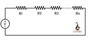
A series circuit has only one path for electric currents to travel through. In this type of circuit, all the different circuit components are linked in a single branch or path of the circuitry.
This article will discuss in detail different basic series circuit examples such as:
Resistor in Series
Suppose there is more than one resistor linked in a series circuit combination. In a series combination, the resistor is linked in such a way that the terminal of one resistor is connected to the terminal of the following resistor resulting in only one path for current to flow through.
The value of resistance increases with the increasing number of resistors in series combination. The current magnitude through each resistor remains constant, where is the voltage or potential drop across each resistor depends upon the magnitude resistance of each resistor.
If the resistors linked in the series are of identical values, then the potential drop across individual resistors will be identical, as the current flowing across each resistor is the same.
The equivalent resistance represents the overall resistance effect of the resistors in the series combination.

Capacitors in Series
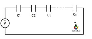
Suppose there is more than one capacitor connected in such a way that the terminal of one capacitor is linked to the terminal of the following capacitor resulting in only one path for current to flow.
The overall capacitance decreases as the number of capacitors increases in a series combination.

As the current magnitude through each capacitor is the same, the charge stored by each capacitor will be the same regardless of the value of the capacitor’s capacitance. At the same time, the potential drop across each capacitor will depend upon the value of each capacitor’s capacitance.
Inductor in Series
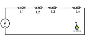
Suppose there is more than one inductor connected in a series combination such a way that one terminal of the inductor is connected to another terminal of the inductor resulting in only one path for current to flow.
The voltage or potential drop across individual inductors is not equal, whereas the current flowing through individual inductors is identical in the series combination.

The total or equivalent inductance is the summation of the individual inductance of each inductor connected in series as the number of turns of coils increases with the addition of the inductor.
Resistor and Capacitor in series
Resistor and capacitor can also be linked in a series combination with each other.
If there is at least one resistor and one capacitor connected in series with each other, then the resulting circuit will be first-order circuitry.
The overall importance of the RC series circuit

Where is Z is the overall impedance
R is the resistance of the resistor
XC is the impedance of the capacitor
The phase angle of the RC series circuit is

In this RC series circuit, the overall voltage lags current, the angle between voltage and current depends upon the value of resistance and the impedance generated by the capacitor.
Resistance and Inductor in series
The resistor and inductor can also be connected in a series combination with each other.
When there is only one resistor and one inductor in the circuitry, it is the first-order RL circuit.
The overall impedance of the RL series circuit is

Where R is the resistance of the resistor
And XL is the impedance generated by the inductor.
The phase angle of the RL series circuit is equal to

The overall voltage leads to current in the RL series circuit, and the angle between the voltage and current depends on the value of the resistance and impedance generated by the overall circuitry.
RLC (Resistance, Inductor and Capacitor) Series
In an RLC series circuit, at least one resistor, one capacitor, and one inductor are connected in series combination with each other.
The current across each circuit element in the series combination is the same. Still, the total or overall voltage is split across each component’s voltage magnitude depending upon each component’s electrical characteristics.
RLC series is a resonant circuit that resonates at a specific frequency which is called the resonance frequency.
If the inductor impedance is greater than that of the capacitor’s impedance, then the overall circuit voltage leads to current. If the capacitor impedance is greater than the impedance of the inductor, then the overall circuit voltage lags current by some angle. In both cases, the angle value depends on the resistance and impedance generated by the inductor and capacitor.
The overall impedance of RLC series circuit :

The phase angle of the RLC series circuit is equal to

LC (inductor and capacitor) Series
Pure inductor and capacitor can be connected in a series combination. There must be at least one inductor and one capacitor in this combination.
As both the elements are connected in series with each other, the current flowing through each element will be the same, and the overall voltage will be simply the summation of the voltage drop across the capacitor and the inductor.
The total (or overall) impedance of the circuitry is the summation of the impedance of capacitor and inductor in the LC (inductor and capacitor) series circuit.
The overall impedance Z = ZL+ ZC
where

then


Voltage in Series
The current source cannot be combined in a series but can be combined in parallel as the series combination of current sources violates Kirchhoff’s current law.
For example, two voltage sources are linked in a series combination. When the voltage source’s positive terminal is linked together with the negative terminals of the voltage source, the overall voltage combination will be added.
In contrast, when the positive terminal of the voltage source is connected to the negative terminal of another voltage source, then the combination’s overall voltage will subtract from each other; this is based on the sign convention of the voltage source or the direction of the flowing current in the circuitry.
If there is more than one current source connected between two circuit nodes, then the current source is in parallel combination.
FAQ:
Why do we connect circuit in series
The series circuit can be a combination of different circuit elements such as resistance, capacitor, inductor, etc.
When the constant current is required, the series combination is used as the current’s magnitude remains consistent in the series combination, which can be controlled or changed easily.
How does voltage changes in a series circuit
Series circuit is also known as a voltage divider circuit as the overall potential energy gets split into all circuit components.
As the current throughout the series circuit is constant, the value of voltage depends upon the impedance or resistance generated by each circuit element connected in the series combination. That is how the value of voltage changes with the electrical property of each component.
What is the advantage of series circuit?
There are several advantages and disadvantages of a series circuit combination depending on the application or where it is used.
The components connected in a series combination have the same magnitude of current flowing through it. All the components connected in series can be turned on or off by using only one switch. The circuit combination does not get overheated easily, and the circuitry design is very simple relative to the parallel circuit.
I have graduated in Applied Electronics and Instrumentation Engineering. I’m a curious-minded person. I have an interest and expertise in subjects like Transducer, Industrial Instrumentation, Electronics, etc. I love to learn about scientific researches and inventions, and I believe that my knowledge in this field will contribute to my future endeavors.