- Definition of Low Pass Filter
- Circuit Diagram
- Active and Passive Low Pass filter
- What does a LPF do? How does it work?
- Operation
- Frequency Response
- Transfer Function of a LPF
- Designing a LPF
- Corner frequency of a low pass filter
- Ideal & Real Filter
- Low Pass Filter vs High Pass Filter
- Advantages of a LPF
- What are the uses of a low pass filter
- FAQs
Definition of LPF:
“Low pass filter carries lower frequency signals with less resistance and has a constant output gain from zero to a cut-off frequency.”
Generally, a low pass filter does attenuation of frequencies above cut-off points.
Circuit Diagram of a Low Pass Filter:
There are two types of active filter exist, they are-
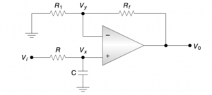
- Active Low Pass Filter – consists of mostly active components like op-amp, a transistor.
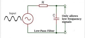
- Passive Low Pass Filter – consists of mostly passive components like capacitors, resistors, etc.
How does a Low Pass Filter Work?
What does a low pass filter do?
In figure 1.1, it’s a commonly used low-pass active filter.
The filtering is commonly done by the RC network, and the op-amp is used as a unity gain amplifier. The resistor RF(= R) is included for Dc offset.
At DC, the capacitive reactance is infinite, and the dc resistive path to ground for both terminals should be equal.
Here, all the voltages Vi, Vx, Vy, V0 are measured concerning ground.
The input impedance of the op-amp is always infinite; no current will flow into the input terminals.

According to the voltage divider-rule, the voltage across the capacitor,

Since the op-amp gain is infinite,
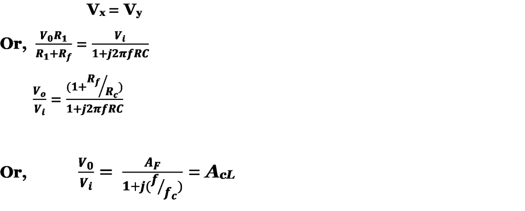
Where,

= pass-band gain of the filter
f = frequency of the input signal

= cut-off frequency of the signal
AcL
= closed-loop gain of the filter as a function of the frequency.
The Gain Magnitude,

And Phase Angle (in degree),

Operation of a Low Pass Filter:
The operation of the low-pass filter can be verified from the gain magnitude equation as follows-
At very low frequencies, i.e., f>>fc,

At f=fc,

|AcL|<AF
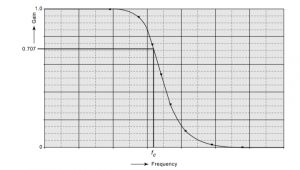
Thus the filter has a constant gain of AF from 0 Hz to the cut-off frequency fc. At fc, the growth is 0.707AF, and after fc, it decreases at a steady rate with an increase in frequency.
Here, the actual response deviates from the linear dashed-line approximation at the vicinity of ‘fc.’
Frequency Response of Low Pass Filter:
How to make a Low Pass Filter?
Low pass filter design:
A value of the cut-off frequency ωc is chosen.
Capacitance C is selected with a certain value; usually, the value is between 0.001 and 0.1µF. Mylar or tantalum capacitors are recommended for better performance.
The value of R is calculated from the relation,

Fc = cut-off frequency in hertz
Ωc = cut-off frequency is in radian second.
C = in Farad
Finally, the values of R1 and RF are selected depending on the desired pass-band gain by using the relation,

Frequency Scaling:- Once a filter is designed, there may be a need to change its cut-off frequency. The method of converting an original cut-off frequency fc to a new cut-off frequency is called ‘frequency scaling.’
To change a cut-off frequency, multiply R or C, but not both by the ratio:-

Corner frequency & Cut-Off Frequency of a Low Pass Filter:
The transition of a low pass filter is always swift and smooth from the pass-band to stopband. Also, a cut-off frequency is not any parameter to measure the goodness or badness in a range of frequency. The cut-off frequency is more accurately referred to as the -3dB frequency, i.e., it is the frequency at which the magnitude response is 3dB lower than the value at 0 Hz.
What is Pass-band?
“Pass-band is the particular range of frequencies which a filter pass through inside it.”
For low pass filters, the frequencies that move towards the end of the pass-band cannot have any significant gain or attention.
What is Stopband?
“A filter always carries filters within a given band, and rejects the frequencies which are below the given range. This particular range is known as a Stopband”.
As the limitations are there for low pass filters, the stopband attenuates at a particular frequency, which moves near the cut-off frequency closer to 0 Hz.
The transfer function of a Low pass Filter:
What is a Transfer Function?
“Transfer function is a complex number that has both magnitude and phase. In the case of filters, transfer function helps to introduce a phase difference between input and output.”
Since low pass filter allows low-frequency AC signals to pass through it, the output gets attenuated. We use different active and passive components to make a filter, which eventually has other characteristics. The transfer function tells us how one input is related to an output depending on the component’s characteristics. The transfer function can easily be determined from a graph of the output signal at various frequencies. We can also calculate the transfer function using Kirchoff’s Laws to derive the filter’s differential equation.

As more signal passes through it, the filter will apply a phase shift to the output signal for the input signal. Hence, the transfer function of a filter is a complex function of frequency. It also contains all the vital information we need to determine the magnitude of the output signal and its phase.
Ideal Filter & Real Filter:
Sometimes, for the reason of simplification, we often use the active filters to approximate ways. We upgrade them into an ideal and theoretical model, which is called ‘Ideal Filter.’
The use of these standards is insufficient, leading to errors; then, the filter should be treated based on accurate real behavior, i.e., as a ‘Real filter.’
The main key terms of an ideal filter are
- A gain unit
- Complete degradation of the input signal across the bands.
- The transition of response from one zone to another is quite abrupt.
- It does not create any distortion when the signal passes through the transit zone.
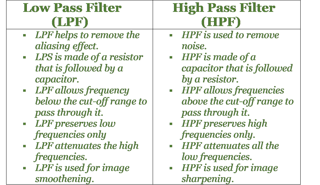
What are the differences between the Low pass filter & High pass filter?
What are the advantages of a Low Pass Filter?
- Low-Pass filters can easily remove aliasing effects from a circuit, which makes the circuit working smoothly.
- Low-Pass Filters are cost-effective so that it can be used easily.
- Low-Pass Filters have low output impedance; thus, it prevents the filters cut-off frequency from being affected because of the load.
Applications of a Low Pass Filter:
- A low-pass filter is used in ‘hiss’ filters.
- LPF is used in audio speakers to reduce high frequency.
- LPF can be used as an audio amplifier and an equalizer.
- In Analog to Digital converter, LPF is used as anti-aliasing filters to control signals.
- LPF is used in image smoothening, image blurring.
- LPF is also used in radio transmitters to block harmonic emissions.
- These filters are used in music systems to filter the high-frequency sounds, causing echo at higher sounds.
What is a passive low pass filter?
A passive low pass filter is a filter made of all passive components like capacitors, resistors, etc. It causes a lesser output level compared to the input level.
What is an RC low pass circuit?
An RC low pass circuit is made of only Resistors and Capacitors, as the name implies. It is an essential passive filter, as well. In this filter, the reactance of a capacitor varies inversely with frequency, and the value of the resistor remains constant as the frequency changes.
What is a Butterworth Low pass Filter?
A Butterworth filter is that type of filter where the frequency response is flat over the pass-band region. A Low-Pass Butterworth filter provides a constant output from DC source to a particular cut-off frequency and rejects the higher level frequencies.
How can a second order low pass filter be constructed?
We know that a first-order low-pass filter can be made by connecting a single resistor and capacitor whose single pole can give us a roll-off slope -20dB/decade. To make a second-order passive low pass filter, we connect or cascade two passive filters (first-order). It is also a two-pole network.
Write down the corner frequency of a second-order filter.
In a second-order low pass filter, we observe a -3dB corner frequency point and therefore, the pass-band frequency changes from its original value as calculated in the equation:

To read more about electronics click here

Hi, I am Soumali Bhattacharya. I have done Master’s in Electronics.
I am currently invested in the field of Electronics and communication.
My articles are focused on the major areas of core electronics in a very simple yet informative approach.
I am a vivid learner and try to keep myself updated with all the latest technologies in the field of Electronics domains.
Let’s connect through LinkedIn –