Contents: Deflection of Beam
- Deflection Curve Definition
- Deflection Angle Definition
- Deflection Definition
- Beam deflection boundary conditions
- Relationship between Loading forces, shear force, bending moment, slope, and deflection
- Beam Bending equations and relations
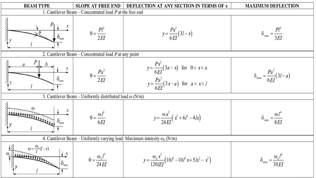
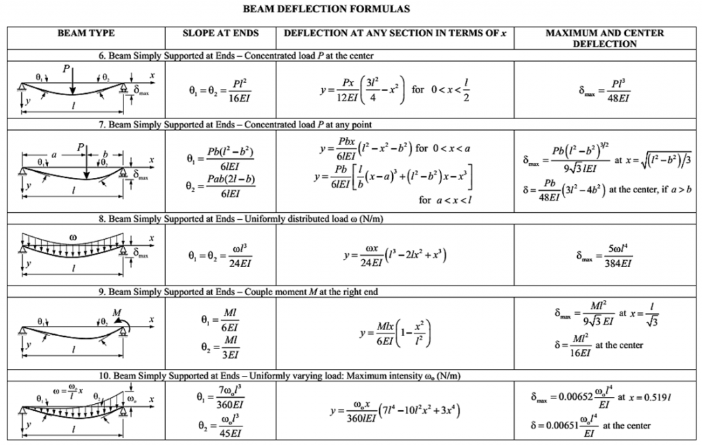
- Beam deflection table and Formulas for standard load cases
- Beam Deflection and slope with examples Case I: Overhanging Beam
- Case II: Determine the maximum deflection of simply supported beam with point load at the center
- Case III: Determine the maximum deflection of simply supported beam with a concentrated point load at a distance ‘a’ from support A
- Double Integration Method
- Procedure for Double Integration Method
- Double integration method for finding beam deflection using Example of a cantilever beam with Uniformly distributed load
- Double integration method for Triangular Loading
In engineering, deflection is the degree to which a structural element is displaced under a load (due to its deformation). It may refer to an angle or a distance. The deflection distance of a member under a load can be calculated by integrating the function that mathematically describes the slope of the deflected shape of the member under that load. Standard formulas exist for the deflection of common beam configurations and load cases at discrete locations. Otherwise methods such as virtual work, direct integration, Castigliano’s method, Macaulay’s method or the direct stiffness method are used.
Deflection Curve
When beams are loaded by lateral or longitudinal loads, the initial straight longitudinal axis is deformed into a curve known as the beam’s elastic curve or deflection curve. The deflection curve is the deformed axis of the selected beam.
Deflection Angle
The slope can be defined as the angle between the beam’s longitudinal axis and the tangent constructed to the beam’s deformation curve at any desired location. It is the angle of rotation of the neutral axis of the beam. It is measured in Radians.
Deflection
Deflection is the translation or displacement of any point on the axis of the beam, measured in the y-direction from the initial straight longitudinal axis to the point on the deflection curve of the beam. It is measured in mm. Deflection represents the deviation of the straight longitudinal axis due to transverse loading. In contrast, buckling of the beam represents the deviation of the initial straight longitudinal axis due to axial compressive load. It is usually represented by ‘y’
If the beam bends like the arc of a circle, it is called circular bending; otherwise, it is called non-circular bending. Suppose a Prismatic beam is subjected to a variable bending moment. In that case, it results in a non-circular type bending, and if it is subjected to constant Bending moment results in circular bending of the beam.
Beam deflection boundary conditions
- y is zero at a pin or roller support.
- y is zero at a built-in or cantilever support.
- Suppose the bending moment and flexural rigidity are discontinuous functions of the x. In that case, a single differential equation cannot be written for the entire beam; the equations of the curve for two adjacent segments should satisfy the given two conditions at the junction between segments:
- 1. The y for the left-hand section must be equal to the y for the right-hand section.
- 2. The slope for the left-hand section must be equal to the slope for the right-hand section.
Relationship between Loading forces, shear force, bending moment, slope, and deflection
Consider a Horizontal Beam AB in unloaded condition. If AB deflects under the load, the new position will be A’B’. The slope at any point C will be
i=\\frac{dy}{dx}
Usually, the deflection is minimal, and for a small radius of curvature,
ds=dx=Rdi
\\\\\\frac{di}{dx}=1/RBut\\;i=\\frac{dy}{dx}Thus,
\\frac{d^2 y}{ dx^2}=1/R According to the simple bending moment theory
\\frac{M}{I}=\\frac{E}{R}\\frac{1}{R}=\\frac{M}{EI}Thus,
\\frac{d^2 y}{dx^2}=\\frac{1}{R}=\\frac{M}{EI}Where,
E = Young’s Modulus of the material
I = Area moment of inertia
M = Maximum Moment
R = Radius of curvature of the beam
This is the Basic differential equation for the deflection of the beam.
Beam Bending equations and relations
Deflection = y
Slope = \\frac{dy}{dx}Bending\\;moment =EI\\frac{d^2y}{dx^2}Shear\\; Force = EI\\frac{d^3y}{dx^3}Load \\;distribution =EI\\frac{d^4y}{dx^4}Beam deflection table and Formulas for standard load cases:
- Maximum slope and deflection in a cantilever beam occur at the free end of the beam, while no slope or deflection is observed on the clamped end of a cantilever beam.
- For a simply supported beam with symmetric loading conditions, the maximum deflection can be found at the midspan. The maximum slope can be observed at the supports of the beam. Maximum deflection occurs where the slope is zero.
Beam Deflection and slope with examples
Case I: Overhanging Beam
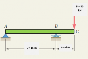
Consider an overhanging steel beam carrying a concentrated load P = 50 kN at end C.
For The overhanging beam, (a) determine the slope and maximum deflection, (b) evaluate slope at 7m from A and maximum deflection from given data I = 722 cm2 , E = 210 GPa.
Solution: The Free body diagram for the given beam is
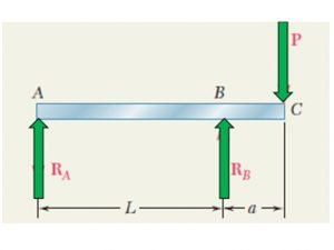
The value of the reaction at A and B can be calculated by applying Equilibrium conditions
\\sum F_y=0\\;\\sum M_A=0
For vertical Equilibrium, Fy = 0
R_A+R_B=P
Taking a moment about A, Clockwise moment positive and Counter Clockwise moment is taken negative.
P(L+a)-R_B*L=0
\\\\R_B=P(1+a/L)
Thus,
R_A+P(1+\\frac{a}{L})=P
R_A= \\frac{-Pa}{L}Consider any section AD at a distance x from support A
The moment at point D is
M= \\frac{-Pa}{L x}Using the differential equation of the curve,
EI \\frac{d^2 y}{dx^2}= \\frac{-Pa}{L x}Integrating twice, we get
EI \\frac{dy}{dx}= \\frac{-1}{2} \\frac{Pa}{L }x^2+C_1……………..[1]EIy=\\frac{-1}{6} \\frac{Pa}{L }x^3+C_1x+C_2……………..[2]We find the constants of integration by using the boundary conditions available to us
At x = 0, y = 0; from equation [2] we get,
C_2=0
At x = L, y = 0; from equation [2] we get,
0=\\frac{-1}{6} \\frac{Pa}{L }*L^3+C_1*L+0C_1= \\frac{PaL}{6}Thus, the equation of slope so obtained by substituting the values of C1 and C2 in [1]
EI \\frac{dy}{dx}= \\frac{-1}{2} \\frac{Pa}{L }x^2+\\frac{PaL}{6}……………..[3]Thus, the equation of deflection so obtained by substituting the values of C1 and C2 in [2]
EIy=\\frac{-1}{6} \\frac{Pa}{L }x^3+\\frac{PaL}{6}x……………..[4]Maximum deflection takes place when the slope is zero. Thus, the location of the point of maximum deflection can be found from [3]:
0= \\frac{-1}{2} \\frac{Pa}{L }x^2+\\frac{PaL}{6} \\frac{1}{2} \\frac{Pa}{L }x^2=\\frac{PaL}{6}x_m=\\frac{L}{\\sqrt 3}x_m=0.577 L
Putting the value of x in equation [4]
EIy_{max}=\\frac{-1}{6} \\frac{Pa}{L }x_m^3+\\frac{PaL}{6}x_mEIy_{max}=\\frac{-1}{6} \\frac{Pa}{L }*0.577 L^3+\\frac{PaL}{6}*0.577 Ly_{max}=0.064\\frac{Pal^2}{EI}Evaluate slope at 7m from A from given data:
I = 722 \\;cm^4=72210^{-8}\\; m^4 , E = 210\\; GPa = 210*10^9\\; PaUsing equation [3]
EI \\frac{dy}{dx}= \\frac{-1}{2} \\frac{Pa}{L }x^2+\\frac{PaL}{6}210*10^9*722*10^{-8}* \\frac{dy}{dx}= \\frac{-1}{2} \\frac{50*10^3*4}{15 }*7^2+\\frac{50*10^3*4*15}{6}\\frac{dy}{dx}=0.5452 \\;radiansmaximum deflection in the beam can be given by
y_{max}=0.064\\frac{Pal^2}{EI}y_{max}=0.064\\frac{50*10^3*4*15^2}{210*10^9*722*10^{-8}}y_{max}=1.89 \\;mCase II: Determine the maximum deflection of simply supported beam with point load at the center.
Consider a simply supported steel beam carrying a concentrated load F = 50 kN at Point C. For the Simply supported beam, (a) evaluate slope at A and maximum deflection from given data: I = 722 cm4 , E = 210 GPa, L =15 m
The Figure below shows the FBD for a simply supported beam with Point load on it.

According to standard relations and formula
Slope at the end of the beam can be given by
\\frac{dy}{dx}=\\frac{FL^2}{16EI}\\frac{dy}{dx}=\\frac{50*10^3*15^2}{16*210*10^9*722*10^{-8}}\\frac{dy}{dx}=0.463For a simply supported beam with point load acting at the center, Maximum Deflection can be determined by
y_{max}=\\frac{FL^3}{48EI }y_{max}=\\frac{50*10^3*15^3}{48*210*10^9*722*10^{-8} }y_{max}=2.31 \\;mCase III: For Simply supported beam with a concentrated point load at a distance from support A
Consider a simply supported steel beam carrying a concentrated load F = 50 kN at Point C. For the Simply supported beam, (a) evaluate slope at A and B and maximum deflection from given data: I = 722 cm4 , E = 210 GPa, L =15 m, a = 7 m, b = 13 m
The Figure below shows the FBD for a simply supported beam with Point load on it.

According to standard relations and formula
Slope at the support A of the beam can be given by
\\theta_1=\\frac{Fb(L^2-b^2)}{6LEI}\\theta_1=\\frac{50*10^3*13*(20^2-13^2)}{6*20*210*10^9*722*10^{-8}}\\theta_1=0.825 \\;radians
The slope at the support B of the beam can be given by
\\theta_2=\\frac{Fab(2L-b)}{6LEI}\\theta_2=\\frac{50*10^3*7*13*(2*20-13)}{6*20*210*10^9*722*10^{-8}}\\theta_2=0.675 \\;radians
For a simply supported beam with point load acting at the center, Maximum Deflection can be determined by
y_{max}=\\frac{50*10^3*13}{48*210*10^9*722*10^{-8} }*(3*15^2-4*13^2)y_{max}=-8.93*10^{-3}\\; m=-8.93\\;mmDouble Integration Method
If Flexural rigidity EI is constant and the moment is the function of distance x, Integration of EI (d2 y)/(dx2 )=M will yield Slope
EI \\frac{dy}{dx}=\\int M dx+C_1EIy=\\int \\int Mdxdx+C_1x+C_2
where C1 and C2 are constants. They are determined by using the boundary conditions or other conditions on the beam. The above equation gives the deflection y as a function of x; it is called the elastic or deformation curve equation.
The above analysis method of deflection and slope of the beam is known as the double-integration method for calculating beam deflections. If the bending moment and flexural rigidity are continuous functions of the x, a single differential equation can be noted for the entire beam. For a statically determinate Beam, there are two support reactions; each imposes a given set of constraints on the elastic curve’s slope. These constraints are called boundary conditions and are used to determine the two constants of integration.
Double integration method boundary conditions
- y is zero at a pin or roller support.
- y is zero at a built-in or cantilever support.
- Suppose the bending moment and flexural rigidity are discontinuous functions of the x. In that case, a single differential equation cannot be written for the entire beam; the equations of the curve for two adjacent segments should satisfy the given two conditions at the junction between segments:
- 1. The y for the left-hand section must be equal to the y for the right-hand section.
- 2. The slope for the left-hand section must be equal to the slope for the right-hand section.
Procedure for Double Integration Method
- Draw the elastic curve for the beam and consider all the necessary boundary conditions, such as y is zero at a pin or roller support and y is zero at a built-in or cantilever support.
- Determine the bending moment M at an arbitrary distance x from the support using the sections’ method. Use appropriate Bending Moment rules while finding Moment M. for a discontinuous moment, the equations of the curve for two adjacent segments should satisfy the given two conditions at the junction between segments: 1. The y for the left-hand section must be equal to the y for the right-hand section. 2. The slope for the left-hand section must be equal to the slope for the right-hand section.
- Integrate the equation twice to get the slope and deflection, and don’t forget to find the constant integration for every section using boundary conditions.
Examples of double integration method for finding beam deflection
Consider the Cantilever beam of length L shown in the Figure below with Uniformly distributed load. In a Cantilever beam, one end is Fixed while another end is free to move. We will derive the equation for slope and bending moment for this beam using the Double integration method.
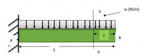
The bending moment acting at the distance x from the left end can be obtained as:
M=-wx* \\frac{x}{2}Using the differential equation of the curve,
\\frac{d^2y}{dx^2}=M = \\frac{-wx^2}{2}Integrating once we get,
EI \\frac{dy}{dx}= \\frac{-wx^3}{6}+C_1………..[1]Integrating equation [1] we get,
EIy= \\frac{-wx^4}{24}+C_1 x+C_2……..[2]The constants of integrations can be obtained by using the boundary conditions,
At x = L, dy/dx = 0; since support at A resists motions. Thus, from equation [1], we get,
C_1=\\frac{wL^3}{6}At x = L, y = 0, No deflection at the support or fixed end A Thus, from equation [2], we get,
0= \\frac{-wL^4}{24}+\\frac{wL^3}{6} *L+C_2C_2= \\frac{-wL^4}{8}Substituting the constant’s value in [1] and [2] we get new sets of equation as
EI \\frac{dy}{dx}= \\frac{-wx^3}{6}+\\frac{wL^3}{6}………..[3]EIy= \\frac{-wx^4}{24}+\\frac{wL^3}{6} -\\frac{wL^4}{8}……..[4]evaluate slope at x = 12 m and maximum deflection from given data: I = 722 cm4 , E = 210 GPa, L =20 m, w = 20 N-m
From the above equations: at x = 12 m,
EI \\frac{dy}{dx}= \\frac{-wx^3}{6}+\\frac{wL^3}{6}210*10^9*722*10^{-8}* \\frac{dy}{dx}= \\frac{-20*12^3}{6}+\\frac{20*20^3}{6}\\frac{dy}{dx}=0.01378 \\;radiansFrom equation [4]
EIy= \\frac{-wx^4}{24}+\\frac{wL^3}{6} -\\frac{wL^4}{8}210*10^9*722*10^{-8}*y= \\frac{-20*12^4}{24}+\\frac{20*20^3}{6} -\\frac{20*20^4}{8}y=-0.064 \\;m
Double integration method for Triangular Loading
Consider the Simply supported beam of length L shown in the Figure below with Triangular Loading. We will derive the equation for slope and bending moment for this beam using the Double integration method.
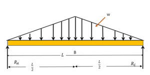
Since the loading is symmetric, each support reaction will bear half of the total loading. The reaction at A and B are found to be wL/4.
Moment at any point at a distance x from RA is
M=\\frac{wL}{4} x- \\frac{wx^2}{L}\\frac{x}{3}=\\frac{w}{12L} (3L^2 x-4x^3 ) \\frac{d^2 y}{dx^2}=M=\\frac{w}{12L} (3L^2 x-4x^3 ) Integrating twice will get us the equations,
EI \\frac{dy}{dx}=\\frac{w}{12L}(\\frac{3L^2x^2}{2}-x^4)+C_1...........................[1]EIy=\\frac{w}{12L} (\\frac{L^2x^3}{2}-\\frac{x^5}{5})+C_1 x+C_2……..[2]At x = 0, y = 0; from equation [2] we get,
C_2=0
Due to symmetry of Load, the slope at midspan is zero. Thus, dy/dx = 0 at x = L/2
0=\\frac{w}{12L}(\\frac{3L^2*L^2}{2*4}-(L^4/16))+C_1C_1=\\frac{-5wL^3}{192}Substituting the constants value in [1] and [2] we get,
EI \\frac{dy}{dx}=\\frac{w}{12L}(\\frac{3L^2x^2}{2}-x^4)+\\frac{-5wL^3}{192}...........................[3]EIy=\\frac{w}{12L} (\\frac{L^2x^3}{2}-\\frac{x^5}{5})+\\frac{-5wL^3}{192} x……..[4]The Maximum deflection will be observed at the center of the beam. i.e., at L/2
EIy=\\frac{w}{12L} (\\frac{L^2(L/2)^3}{2}-\\frac{(L/2)^5}{5})+\\frac{-5wL^3}{192}(L/2)EIy_{max}=\\frac{w}{12L} (\\frac{L^5}{16}-\\frac{L^5}{160})+\\frac{-5wL^4}{384}EIy_{max}=\\frac{-wL^4}{120}evaluate slope at x = 12 m and maximum value of y from given data: I = 722 cm4 , E = 210 GPa, L =20 m, w = 20 N-m
From the above equations: at x = 12 m,
EI \\frac{dy}{dx}=\\frac{w}{12L}(\\frac{3L^2x^2}{2}-x^4)+\\frac{-5wL^3}{192}210*10^9*722*10^{-8}* \\frac{dy}{dx}=\\frac{20}{12*20}(\\frac{3*20^2*12^2}{2}-12^4)+\\frac{-5*20*20^3}{192}\\frac{dy}{dx}=8.60*10^{-4 } \\;radiansFrom equation [4]
EIy_{max}=\\frac{-wL^4}{120}210*10^9*722*10^{-8}*y=\\frac{-20*20^4}{120}y=-0.01758\\;m
To know about Strength of material(click here)and Moment Area method Click here.

I am Hakimuddin Bawangaonwala , A Mechanical Design Engineer with Expertise in Mechanical Design and Development. I have Completed M. Tech in Design Engineering and has 2.5 years of Research Experience. Till now Published Two research papers on Hard Turning and Finite Element Analysis of Heat Treatment Fixtures. My Area of Interest is Machine Design, Strength of Material, Heat Transfer, Thermal Engineering etc. Proficient in CATIA and ANSYS Software for CAD and CAE. Apart from Research.
