Content
· Analog to digital converter (ADC)
· Working Principle of an analog to digital converter
· Electrical Symbol of analog to digital converter
· Types of analog-to-digital converter & Explanations
· Applications of analog to digital converter
· Testing of an analog-to-digital converter
· An ADC IC
Definition & Overview of Analog-to-digital Converter
An analog to digital converter is an electronic device. As the name predicts, the supplied analog signal is converted into a digital signal which is produced at output. Analog signals such as voice recorded by a microphone can be converted into a digital signal using an analog-to-digital converter.
An analog to digital converter is also known as ADC and A to D converter, etc.
Working of an Analog to digital converter
An analog signal is defined as the time-continuous and continuous-amplitude signal. At the same time, a digital signal is defined as the discrete-time and discrete-amplitude signal. An analog signal is converted into a digital signal with the help of an analog-to-digital converter. The transformation has several steps, like sampling, quantization, and others. The process is not continuous; instead, it is periodic and limits the input signal’s allowable bandwidth.
An analog-to-digital converter works based on the Nyquist-Shannon Sampling Theorem. It states that – an input signal can be recovered from its sampled output if the sampling rate is twice greater than or equal to the highest frequency component present in the input signal.
There are several parameters to measure the performance of an analog to digital converter. The bandwidth of the output signal, the signal to noise ratio are some of the parameters.
Electrical Symbol of an ADC
The below symbol represents an Analog to digital converter (ADC).

Types of Analog to digital converters
The conversion of input analog signals into digital signals can be achieved through different processes. Let’s discuss some of the types in detail –
A. Flash ADC
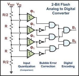
Flash ADC is known as direct-conversion type’s analog to digital converter. It is one of the fastest types of analog-to-digital converters. It comprises a series of comparators with the inverting terminals connected to a voltage divider ladder and the non-inverting terminals connected to the analog input signal.
As the circuit shows, a ladder of well-matched resistors is connected with a reference or threshold voltage. A comparator is used at each tap of the resistors’ ladder. Then there is an amplification stage, and after that, the code is generated as binary values (0 and 1). An amplifier is also used. The amplifier amplifies the voltage difference from the comparators and also suppresses the comparator offset.
If the measured voltage is above the threshold voltage, then the binary output will be one, and if the measured voltage is less than the binary work will be 0.
Recently improved ADCs are modified with digital error corrections systems, offset calibrations, and also, they are a smaller size. ADCs are now available in integrated circuits (ICs).
This type of analog-to-digital converters has a high sampling rate. Thus, it has applications in high-frequency devices. Detection using radars, wide-band radios, various testing equipment are some of them. NAND Flash memory also uses flash type analog-to-digital converters to store up to 3 bits in a cell.
Flash type ADCs are fastest in operation speed, simple in circuitries, and conversion coincides instead of sequentially. Though, these requires considerable numbers of comparisons than different types of ADCs.
B. Successive Approximation type ADC
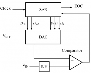
Successive approximation type ADC is another type of analog-to-digital converter which uses binary search through quantization levels before conversion into the digital domain.
The whole process is divided into different sub-processes. There is an ample and hold circuit, which takes the analog input, Vin. Then there is a comparator that compares the input analog voltage with the internal digital-to-analog converter. There is also a successive-approximation register (SAR), which takes input as clock pulse and comparator data.
The SAR is primarily initialized to make the MSB (most significant bit) as logic high or 1. This code is supplied to the digital-to-analog converter, which further provides the analog equivalent to the comparator circuit compared to the sampled analog input signal. If the voltage is more than the input voltage, then the comparator resets the bit. Else the bit is left as it is. After that, the next bit is set to a digital one, and the whole process is again done until every bit of the successive-approximation register is tested. The final output is the digital version of the analog input signal.
There are two types of successive-approximation types analog-to-digital converters available. They are – Counter type and Servo tracking type.
These types of ADCs give the most accurate results than other types of ADC.

Image Credit :White Flye, SA ADC block diagram, CC BY-SA 2.5
C. Integrating type ADC
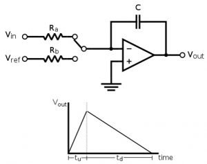
As the name implies, this type of ADCs converts continuous-time and continuous amplitude input analog signal into a digital signal using an integrator (an integrator) to apply an operational amplifier that takes a usual input signal and gives time-integrated output signal).
An unidentified analog input voltage is applied at the input terminal and allowed to ramp for a certain period, known as the run-up period. A pre-determined reference voltage of opposite polarity is then applied to the integrator circuit. That is also allowed to ramp until and unless the integrator gives the output as zero. This time is known as the run-down period.
The run-down time is generally measured in units of the ADC’s clock. So, longer integration time results in higher resolution. The speed of this type of converter can be improved by compromising with the solution.
As the speed and resolution are inversely proportional, this type of converters does not find digital signal processing or audio processing applications. Preferably, they are used in digital measurement meters (ammeters, voltmeters, etc.) and other instruments where high accuracy is crucial.
This type of ADCs has two kinds – charge balancing analog to digital converter and Dual-slope ADC.

D. Wilkinson ADC
– D. H. Wilkinson first designed this type of analog-to-digital converter in the year 1950.
At first, capacitor gets charged. A comparator checks this condition. After getting to that specified level, now the capacitor starts discharging linearly, producing a ramp signal. A gate pulse is also initiated in the meantime. The gate pulse remains on for the rest of the time while the capacitor discharges. This gate pulse further operates a linear gate which further receives input from an oscillator clock of high-frequency. Now, when the gate pulse is ON, several clock pulses are being counted by the address register.
E. Time Stretch Analog to Digital Converter (TS – ADC):
This type of Analog-to-digital converter are functioned on a combined technology of electronics and other techs.
It can digitalize a very high bandwidth signal that cannot be done using an ordinary ADC. This is often termed as “Photonic Time Stretch Digitizer”.
It not only analog to digital but also used for high-throughput real-time equipment such as imaging and spectroscopy.
There are several other types of other analog-to-digital converters.
- The Delta-encoded ADC
- The Pipelined ADC,
- The Sigma-delta ADC,
- The Time-interleaved ADCs etc.
What is DAC? Know more about Digital to analog converter! Click to know!
Applications of ADC
The analog to digital converter is one of the most important electronic devices in this modern era. This is an era of digitalization, but our world is analog in real-time. Converting analog data in the digital domain is the need of this hour. That is why they are so important. Some of the significant applications of an ADC are –
A. Digital signal processing
– Analog to digital converters are essential for editing, modifying, processing, storing, and transporting data from the analog field to the digital area. Microcontrollers, digital oscilloscopes, and critical software find applications in this domain. Devices like digital oscilloscopes can store waveforms for later use, whereas an analog oscilloscope cannot.
B. Microcontrollers
– Microcontrollers makes a device smart. At present, almost all microcontrollers have analog to digital converters inside them. The most common example may be the Arduino. (It is built on an ATMega328p microcontroller) The Arduino provides a useful function of ‘analogRead(),’ which takes analog input signals and returns digital data generated by the ADC.
C. Scientific Instruments
– ADCs are useful for making various necessary electronics instruments and systems. Digital imaging for the digitization of pixels, radar technologies, and many remote sensing systems is an example. Devices like sensors produce an analog signal for measuring temperature, light intensity, light sensitivity, air humidity, air pressure, pH of a solution, etc. All these analog inputs are converted by ADC to generate a proportionate digital output.
D. Audio Processing:
-ADC has a vital application in the field of audio processing. The digitization of music enhances music quality. Analog voices are recorded via microphones. Then they are stored in digital platforms using an ADC. Many tunes recording studios record in PCM or DSD formats and then down sampled for digital audio productions. They are used for broadcast on televisions and radios.
Testing of an analog to digital converter
To test an analog-to-digital converter, first of all, we need an analog input voltage source and electronics equipment to send and control signals and receive the digital output data. Some of the ADCs also requires a source of reference signals. There are some parameters to test an ADC.
Some of them are –
- Signal to noise ratio (SNR),
- Total harmonic distortion (THD),
- Integral nonlinearity (INL),
- DC offset error,
- DC gain error,
- Power Dissipation, etc.
ADC IC
ADCs are commercially available as ICs in the market. Some of the commonly used ADC ICs are ADC0808, ADC0804, MPC3008, etc. They find applications in devices like Rasberry pi and other processors or digital electronics circuits where an ADC is needed.
To know more about electronics click here

Hi, I am Sudipta Roy. I have done B. Tech in Electronics. I am an electronics enthusiast and am currently devoted to the field of Electronics and Communications. I have a keen interest in exploring modern technologies such as AI & Machine Learning. My writings are devoted to providing accurate and updated data to all learners. Helping someone in gaining knowledge gives me immense pleasure.
Let’s connect through LinkedIn –
